Line connection and line-side power components
3.11 Line connection variants
Booksize Power Units
Manual, (GH2), 07/2016, 6SL3097-4AC00-0BP8
143
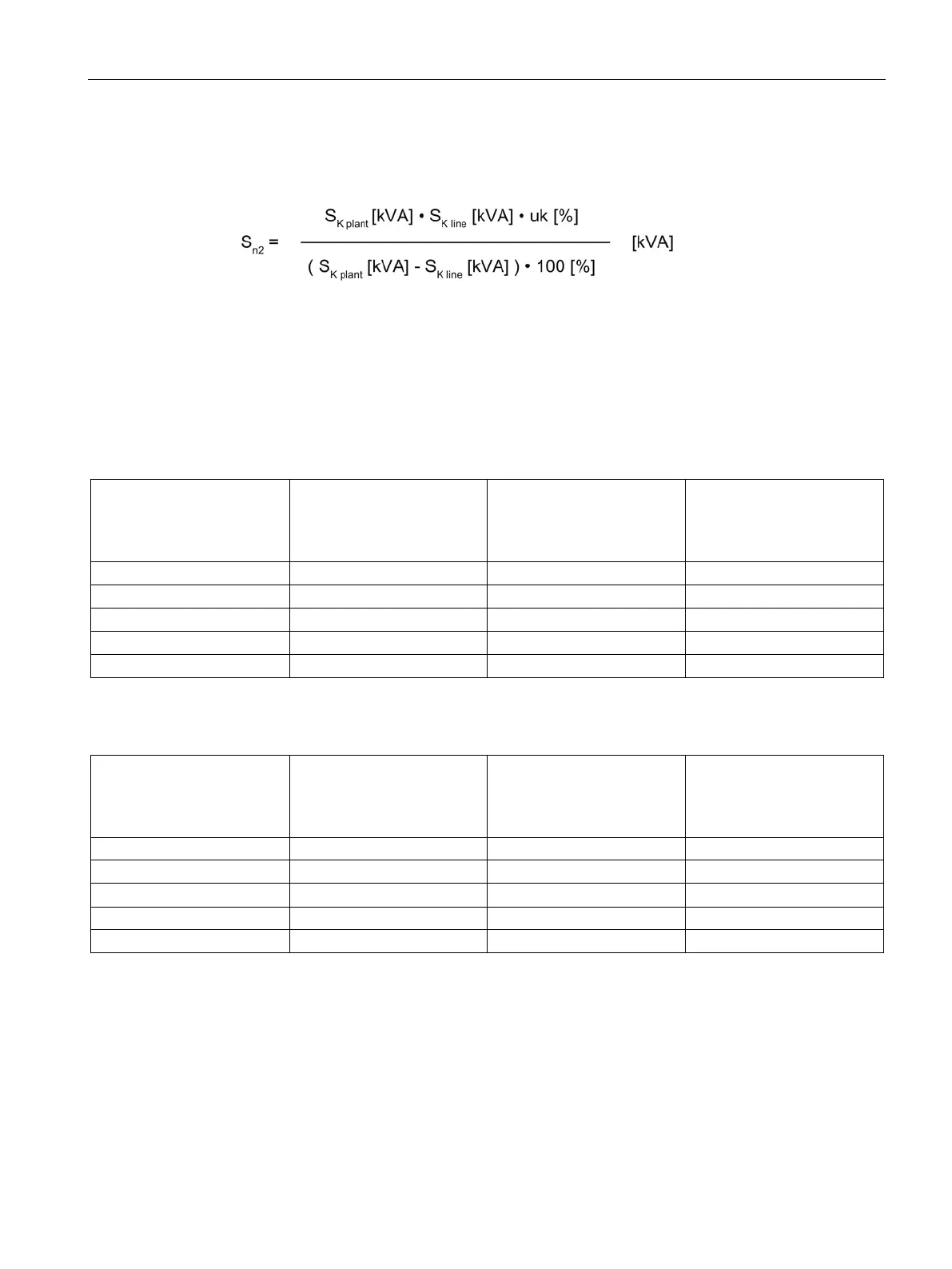
The required rated power of the matching transformer can be calculated with the following
formula.
The short-circuit power at the plant connection S
K factory
plays a decisive role in dimensioning
the matching transformer.
From the rated power (S
n1
or S
n2
) calculated under a) and b), the higher value must be used
for the matching transformer.
Table 3- 32 Engineering information for transformers for Active Line Modules
Required rated power of the
isolating transformer / auto-
transformer
S
n
(1.27 • P
n
)
Required short-circuit volt-
age U
k
Minimum system fault level
required
S
K line
(70 • P
n
)
Table 3- 33 Engineering information for transformers for Smart Line Modules
Required rated power of the
isolating transformer / auto-
transformer
S
n
(1.27 • P
n
)
Required short-circuit volt-
age U
k
Minimum system fault level
required
S
K line
(70 • P
n
)
16 kW ≥ 21 kVA ≤ 3 % ≥ 1.12 MVA

 Loading...


