Line Modules Booksize
4.11 Smart Line Modules with cold plate
Booksize Power Units
316 Manual, (GH2), 07/2016, 6SL3097-4AC00-0BP8
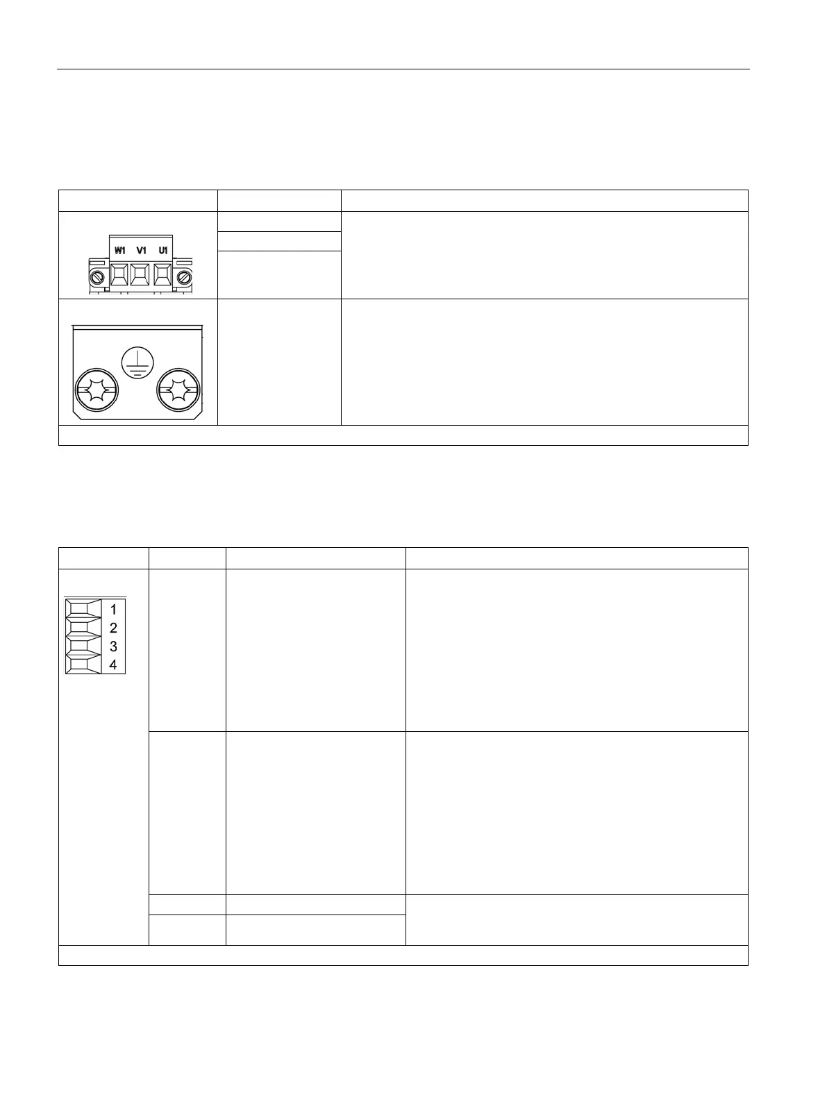
Table 4- 86 X1 line connection
Supply voltage:
3 AC 380 … 480 V, 50 / 60 Hz
Type: Screw terminal 5 (Page 730)
W1
PE connection Threaded hole M5 / 3 Nm
1
1)
For ring cable lugs without insulation (Page 732)
Table 4- 87 X21 EP terminals
1 DO: Ready Feedback signal: Smart Line Module ready
The signal switches to high level when the following condi-
tions have been met:
• Electronics power supply (X24) OK
• DC link is precharged
• Pulses enabled (X21.3/.4)
• No overtemperature
• No overcurrent switch-off
2 DO: Prewarning
DO: Prewarning
High = no prewarning
Low = prewarning
• Overtemperature warning threshold / I*t
5 kW prewarning: 64° C, disconnection: 69° C
10 kW prewarning: 68° C, disconnection: 73° C
• No regenerative feedback capability due to a line fault
[only monitored when feedback is activated (see termi-
nal X22.2)]
Voltage: 24 V DC (20.4 ... 28.8 V)
Current consumption, typical: 4 mA at 24 V
4 EP M (Enable Pulses)
Type: Screw terminal 1 (Page 730)

 Loading...


