DC link components
8.6 Control Supply Module CSM
Booksize Power Units
Manual, (GH2), 07/2016, 6SL3097-4AC00-0BP8
537
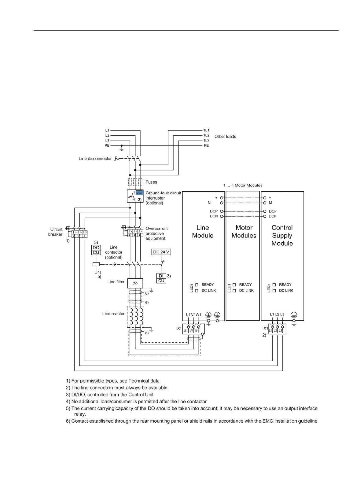
Within the drive line-up, the Control Supply Module must be connected to the drive line-up
via the DC link busbars as well as the 24 V busbars. The 24 V connector from the
accessories pack must always be inserted. The DIP switch on the Control supply Module
must be set to "single mode" The connection can be established as shown below.
The supply for other 24 V loads outside the drive line-up using additional Control Supply
Modules, whose outputs are not connected in parallel, must be realized using the 24 V
terminal adapter (do not insert the 24 V connector).
Figure 8-22 Connection example for Control Supply Module in single operation

 Loading...


