Braking resistors
9.4 Technical data
Booksize Power Units
Manual, (GH2), 07/2016, 6SL3097-4AC00-0BP8
559
Max. energy consumption
E
max
at P
max
n
kWs
kWs
22.5
100
45
200
90
400
225
1000
Thermostatic switch connec-
tion
Screw terminal
2)
,
4 mm
2
Screw terminal
2)
,
4 mm
2
Screw terminal
2)
,
2.5 mm
2
Screw terminal
2)
,
1.5 mm
2
Power cable connection Screw terminal
3)
,
2
Screw terminal
3)
,
2
M6 threaded bolts
4)
M6 threaded bolts
3)
Degree of protection to
IP20 IP20 IP20 IP20
Applies to a DC-link voltage of 760 V
Recommended connection cross-section: 0.75 to 1.5 mm
2
Recommended connection cross-section: 2.5 mm
2
Recommended connection cross-section: 4 mm
2
5)
Recommended connection cross-section: 16 mm
2
The MC500 or MC800 motor cable should be used as connecting cable.
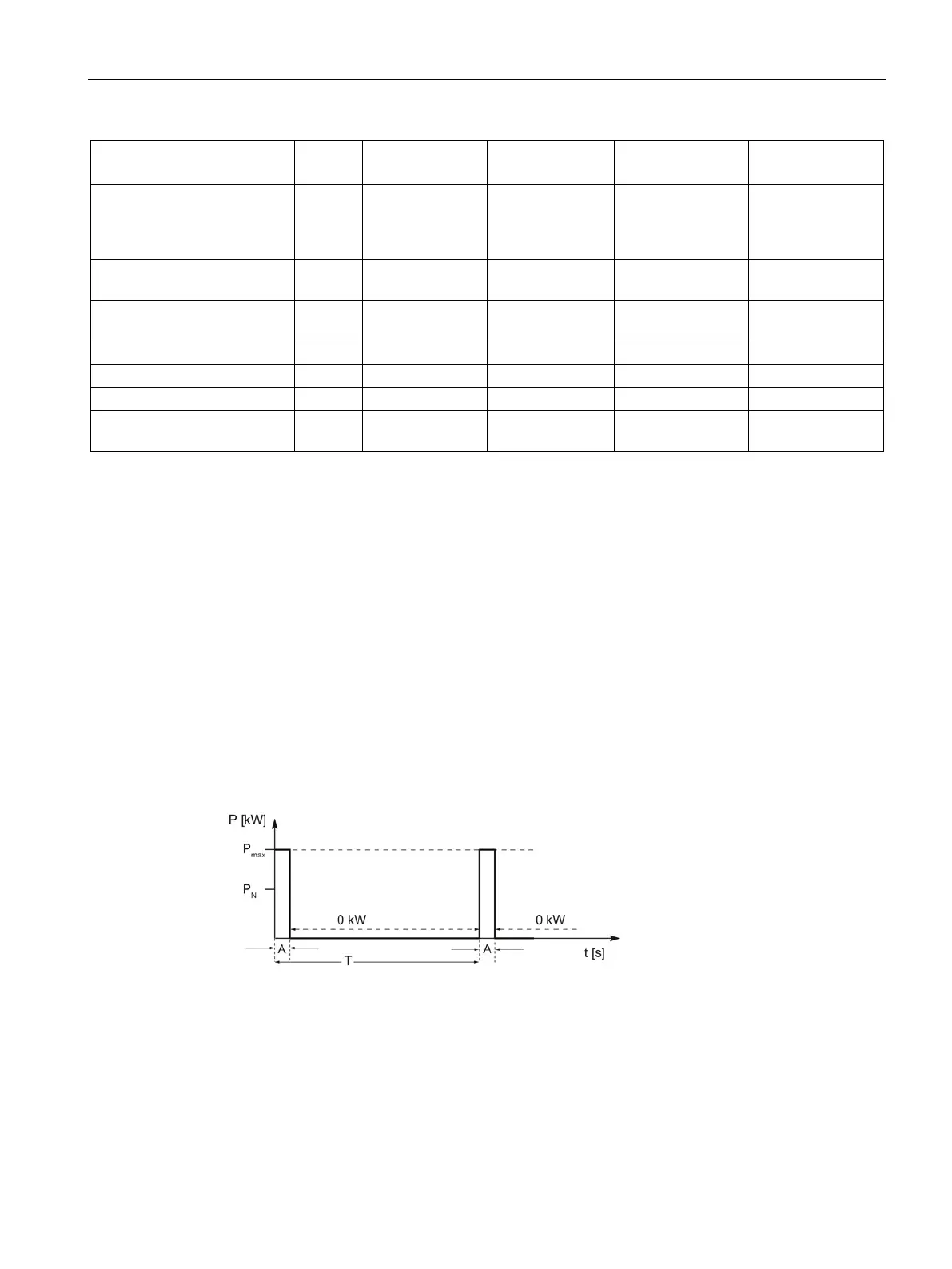
Characteristic curves
Duty cycle for braking resistors without a thermostatic switch
Figure 9-8 Duty cycle for braking resistors without a thermostatic switch
T [s] time period of braking duty cycle
A [s] load duration
P
N
[kW] rated power (continuous power) of the braking resistor
P
max
[kW] peak braking power of the braking resistor

 Loading...


