Cabinet design and EMC Booksize
12.12 Power losses of the components
Booksize Power Units
768 Manual, (GH2), 07/2016, 6SL3097-4AC00-0BP8
Typical power losses for Motor Modules
The information on the power losses in the previous chapters are maximum values, which
occur in the most unfavorable case. For typical applications, the losses are lower.
The following applies as typical application:
● Maximum motor cable length, 30 m
● 4 kHz pulse frequency
● DC link voltage 540 V - 600 V
The power loss for typical applications can be calculated using the following formula:
P
V
[W] = a + S
1
• (I
1
+ I
2
) + S
2
• (I
1
2
+ I
2
2
)
Electronics losses of the Motor Module
1
, S
2
late power loss
1
Current (arithmetic mean value) of the 1st axis
2
Current (arithmetic mean value) of the 2nd axis
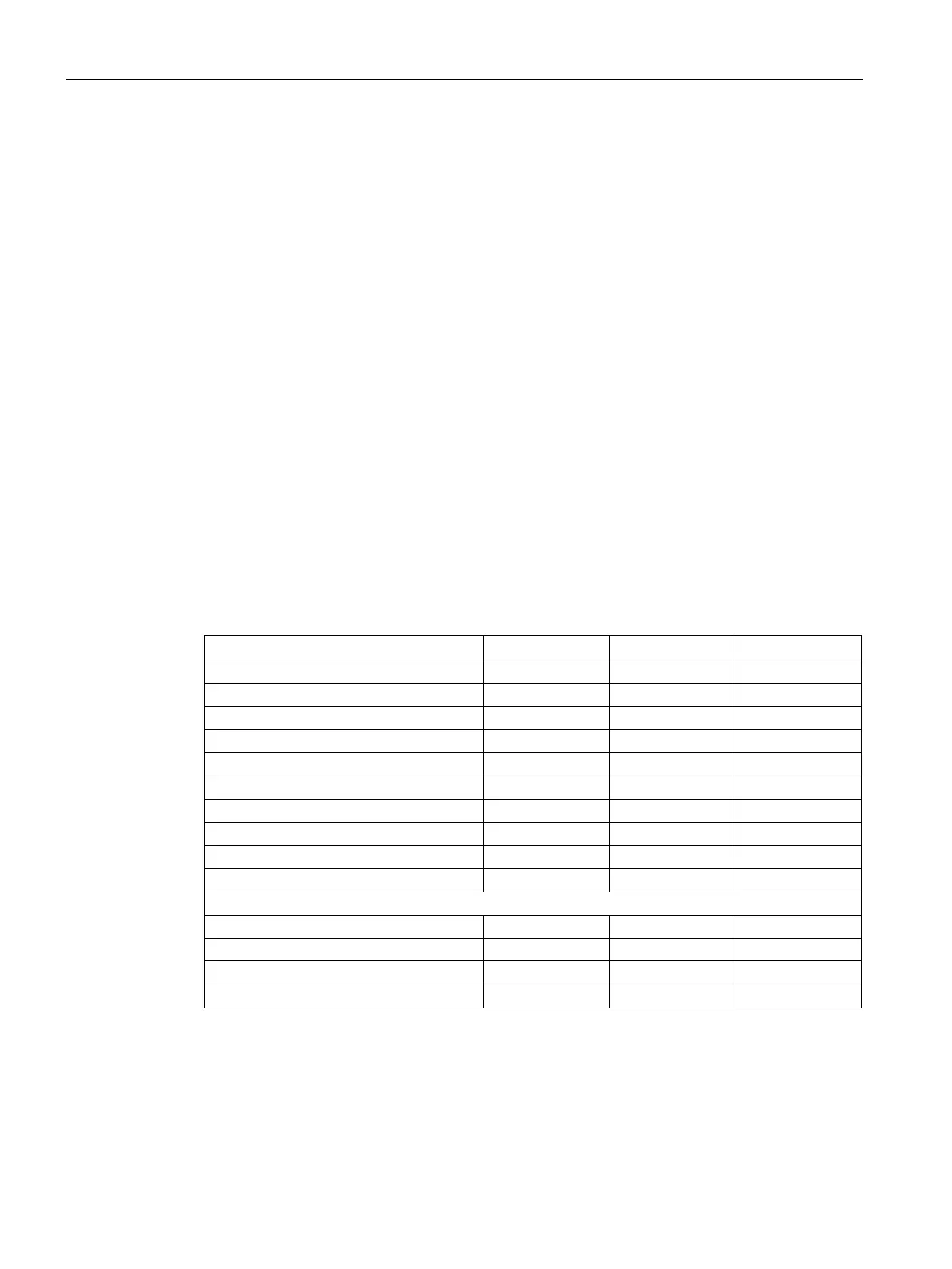
Overview of required coefficients
Table 12- 43 Coefficients to calculate the power loss in the control cabinet for internally cooled Mo-
tor Modules for typical applications
Single Motor Module 132 A
Single Motor Module 200 A
Double Motor Module 18 A 22 5,57 0,091

 Loading...


