Cabinet design and EMC Booksize
12.7 Connection systems
Booksize Power Units
704 Manual, (GH2), 07/2016, 6SL3097-4AC00-0BP8
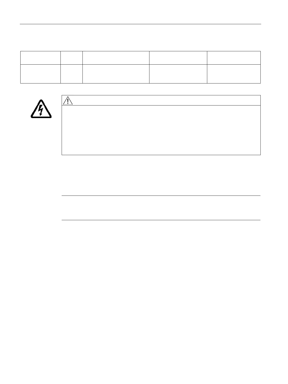
Table 12- 10 Recommendation for Control Supply Module
Rated output cur-
rent [A]
Short-circuit current [A]
20 3 3-phase 380 V AC -10 % (-15 %
< 1 min) to 480 V AC +10%
< 24 6SL3100-1DE22-0AA.
Danger to life through a hazardous voltage when connecting an unsuitable power supply
Touching live components can result in death or severe injury.
• Connect the ground potential to the PE conductor connection.
• Mount the power supply close to the drive lineup.
Ideally, they should be mounted on a common mounting plate. If different mounting
plates are used, they must be electrically connected in compliance with the
Configuration Manual, "EMC installation guideline".
Note
Cables for UL applications
For UL applications, only 60/75
°C copper cables may be used.
DRIVE-CLiQ signal cables
12.7.1.1
To connect DRIVE-CLiQ components, various pre-assembled and non-assembled DRIVE-
CLiQ signal cables are available. The following pre-assembled DRIVE-CLiQ signal cables
will be discussed in more detail in the next sections:
● Signal cables without 24 V cores with RJ45 connectors
● MOTION-CONNECT signal cables with DRIVE-CLiQ connectors
● MOTION-CONNECT signal cables with DRIVE-CLiQ connector and M12 socket

 Loading...


