Cabinet design and EMC Booksize
12.7 Connection systems
Booksize Power Units
726 Manual, (GH2), 07/2016, 6SL3097-4AC00-0BP8
Shield support on a toothed rail
The toothed rail should be mounted at a distance of ≤ 150 mm below the drive line-up to
ensure a good contact. Wherever possible, the brake conductors must be kept physically
separate from U/V/W connections.
Note
Measures must be taken on site to relieve strain on the cables.
The maximum permissible tensi
le load in the insertion direction is 100 N.
With these versions, the shield for the brake connection conductors must be routed together
with the cable shield.
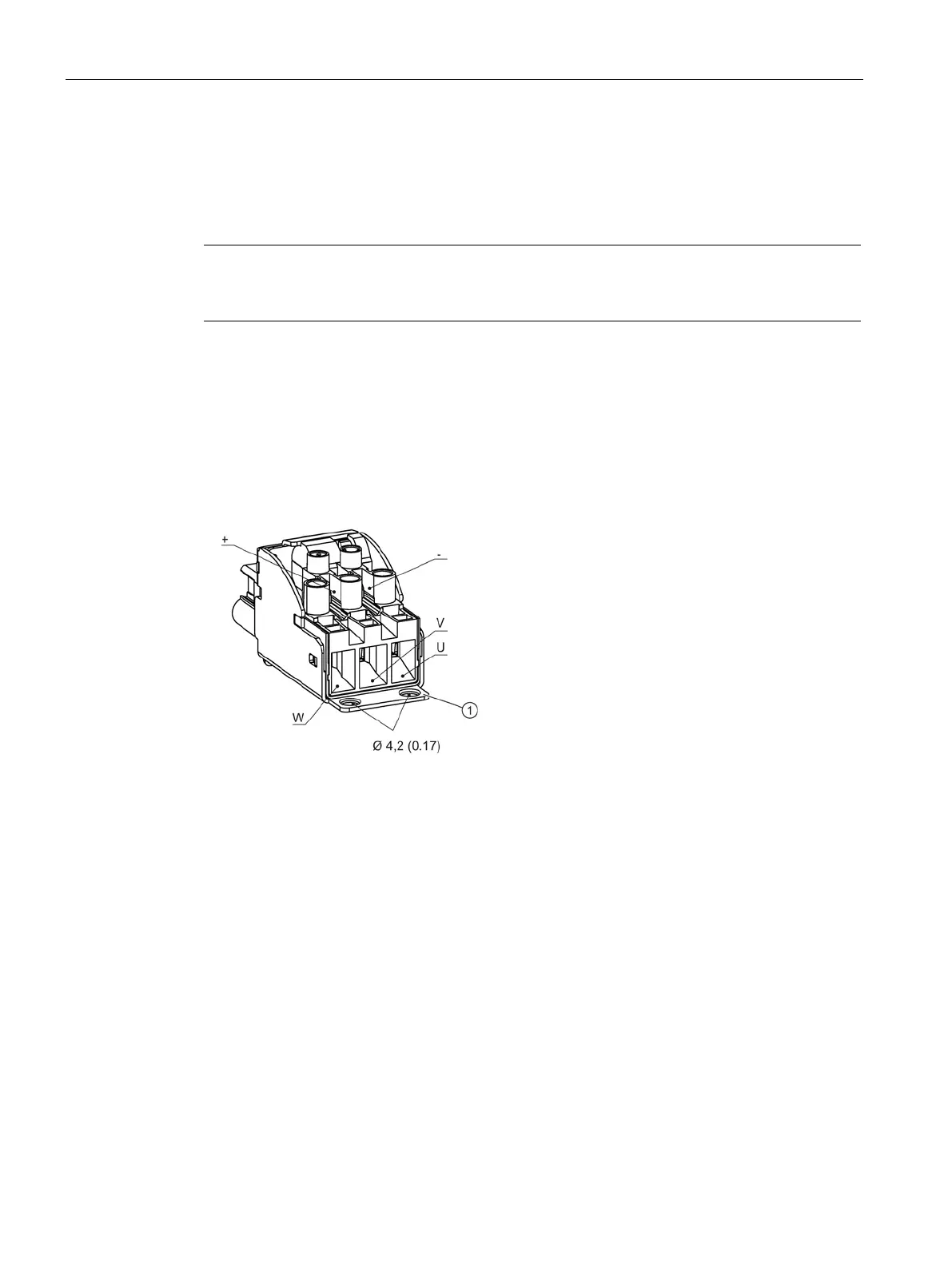
Attaching the motor connector
The connections for the single conductors at the motor connector can be taken from the
following diagram.
Connection for shield plate supplied with the equipment
Figure 12-32 Connections at the motor connector, screw version
The motor connector is connected as shown below.
1. Insert the individual U, V, W conductors into the associated terminals of the motor
connector (maximum cross-section for cables with end sleeves according to DIN 46228-
E: 10.0 mm
2
).
2. Insert the individual conductors of the motor holding brake into the associated terminals
of the motor connector (maximum cross-section for cables with end sleeves according to
DIN 46228-A: 1.5 mm
2
).

 Loading...


