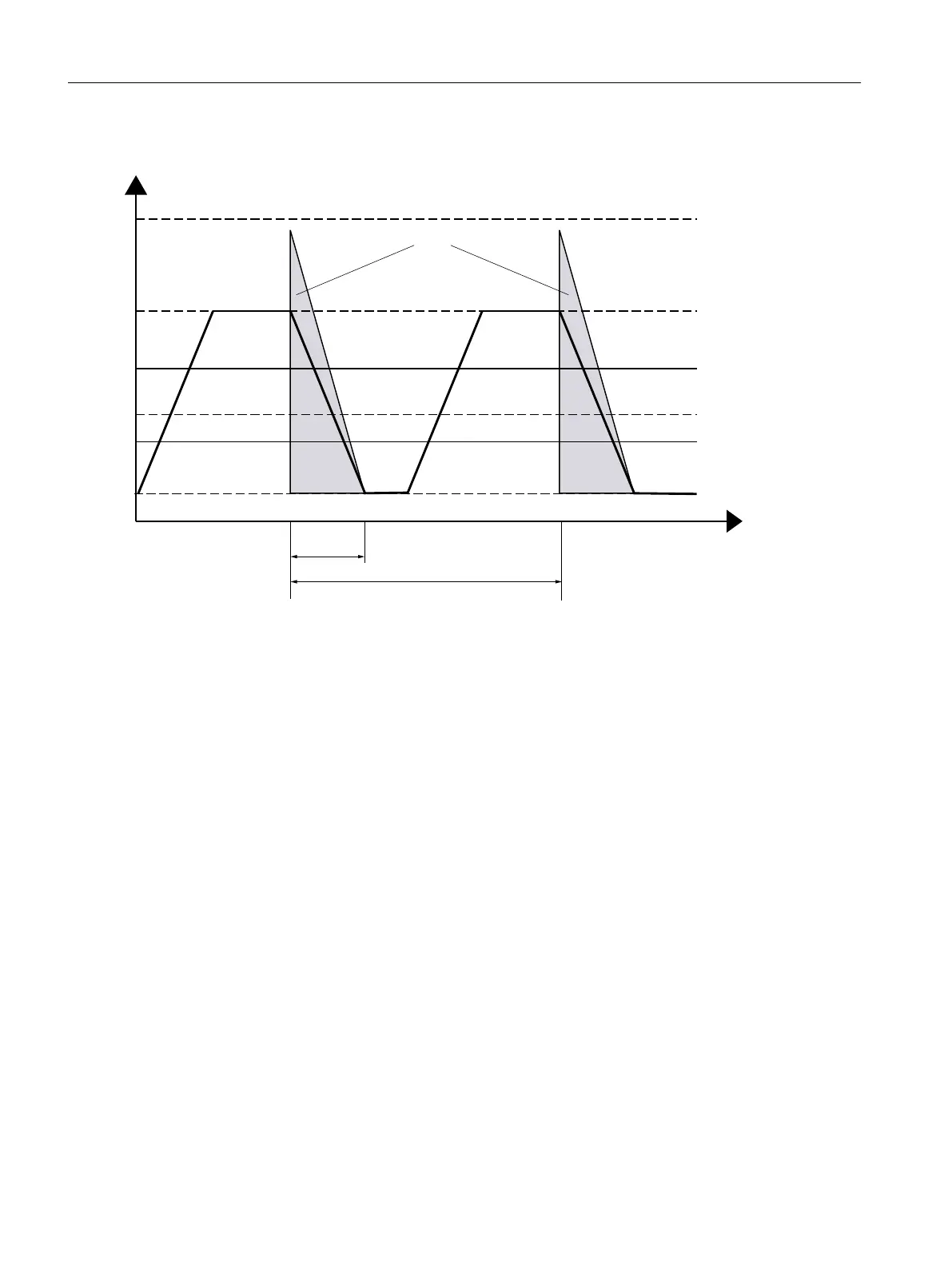
Load cycles for braking resistors
7
3Q
W
Q
Q
3
PD[
3
EU
3
DYJ
3
FRQW
(
EU
W
RQ
P
max
[W]:Maximum peak power
P
cont
[W]:Maximum continuous po
wer
P
br
[W]:Application-specic braking power
P
avg
[W]:Application-specic average braking power
E
max
[J]:Maximum braking energy
E
br
[J]:Application-specic braking energy
t
on
[s]:Braking duration
T [s]:Cycle duration
n
1
[r/min]:Initial speed
n
2
[r/min]:Speed after braking
P
max_int
[W]:Maximum peak power of internal braking resistor
P
max_ext
[W]:Maximum peak power of external braking resistor
P
cont_int
[W]:Maximum continuous power of internal braking resistor
P
cont_ext
[W]: Maximum continuous power of external braking resistor
E
max_int
[J]:Maximum braking energy of internal braking resistor
E
max_ext
[J]:Maximum braking energy of external braking resistor
Figure14-3 Peak power, continuous power and duty cycle of the braking resistor
Technical data
14.1Technical data of the converter
SINAMICS S200 PROFINET servo drive system with SIMOTICS S-1FL2
620 Operating Instructions, 11/2023, FW V6.3, A5E51646752B AB