CD600 Plus - User’s Manual
9.6
SIGNAL CABLE INSTALLATION
Always install the signal cables in separate trays from the power cables. The signal cable installation
and power cable installation on the same tray should satisfy one of the three conditions:
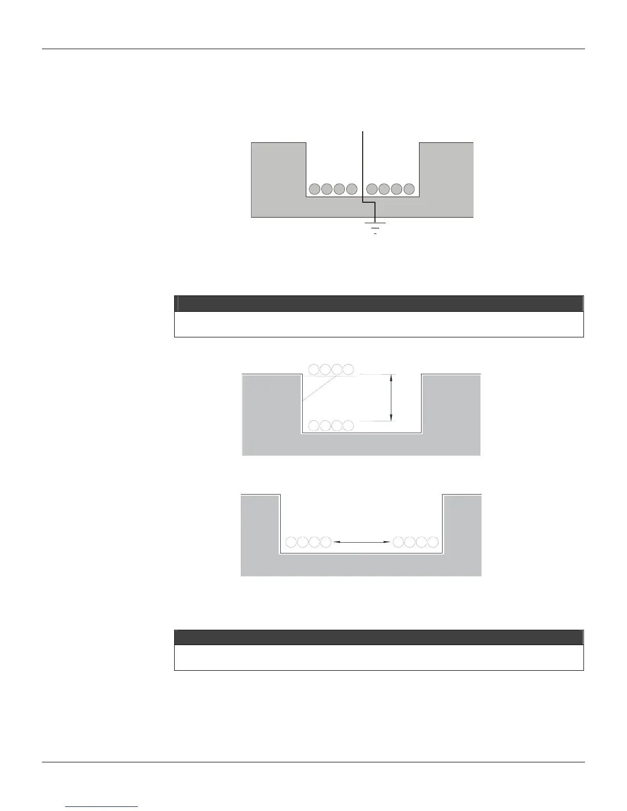
1) Install a grounded metallic separator, as illustrated in figure 9.7.
ISOLATOR
SIGNAL
CABLES
POWER
CABLES
Fig. 9.7 – Cable Arrangements on the Tray
2) Predict a tolerance between the power cables and signal cables, using a cable tray, as illustrated in
figures 9.8 and 9.9.
NOTE
If the power cables operate with a voltage greater than 220 V and a current greater than 10 A, and are NOT
shielded, the distance from the signal cables should be at least 60cm.
Fig. 9.8 – Cable Arrangements on the Tray
I
NAL
ABLE
POWER
CABLES
>
1
5
c
m
Fig. 9.9 - Cable Arrangements on the Tray
SIGNAL
CABLES
POWER
CABLES
>15cm
3) Cross the power cables and the signal as illustrated on figure 9.10.
NOTE
When using non-shielded cables, it is recommended to use a 1.6mm thick iron board between the signal and
power cables as indicated in figure 9.10