Installation
9.5
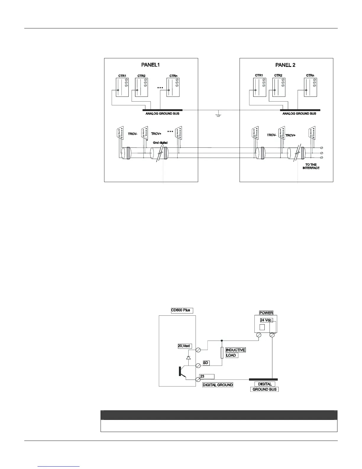
Communication
For each controller on the communication line, a terminal block should be placed, as shown in fig.
9.5.
Fig. 9.5 – Communication cable
Alarm
When the digital outputs are used to activate relays, lamps, solenoids, etc., the following precautions
should be taken:
a) Precautions Using Relays and Solenoids
When activating relays and solenoids through the controller contacts (digital outputs and controller
fail output), make sure that:
• All loads commanded by the digital outputs should be designed for DC voltage (maximum 30 Vdc);
• The maximum current should be 400 mA
• The relays and solenoids are specified with the lowest voltage possible, in order to increase
operation safety;
• The positive terminal from the source, should be connected to terminal 20 (Vext), being
necessary to connect a diode in parallel with the relay and solenoid coils, for inductives loads
generate a reverse voltage on the relay commutation. Without this procedure, this phenomenon
will damage the digital outputs’ signal.
All loads connected to the digital outputs of the same controller, should have the same supply voltage.
Fig. 9.6 – Inductive Loads on the Digital Outputs
NOTE
The last configuration can be used as long as the negative from the power supply ( - ) is isolated from the analog
ground (AGND terminal).