Library of Function Blocks
4.41
LEAD-LAG FUNCTION AND TIME CONSTANT
When operating in the lead-lag mode, the block implements the following transfer function:
)(s I
Ts + 1
s
T
D
+ 1
= )(s O
rted between the disturbance signal (input
ow) and the adder which performs the loop's feedforward.
Figure 4.15.4 shows the response of the open loop system to a step variation in the steam flow rate.
Where,
T
D
- Lead constant, adjusted by parameter ATLE (min.)
T - Lag constant, adjusted by parameter ATLA (min.)
The response to a step function with amplitude A in the input is shown in Figure 4.15.2 for a lag
constant
ATLA=1 and several lead constants (ATLE).
At l e = 2
1.5
1 Input
0.5
0
T
OUTPUT
A
O
+T
TI ME
O (t
O
) .
=O+A
t
O
T
Fig 4.15.2 - Response of the Lead-Lag function to a Step
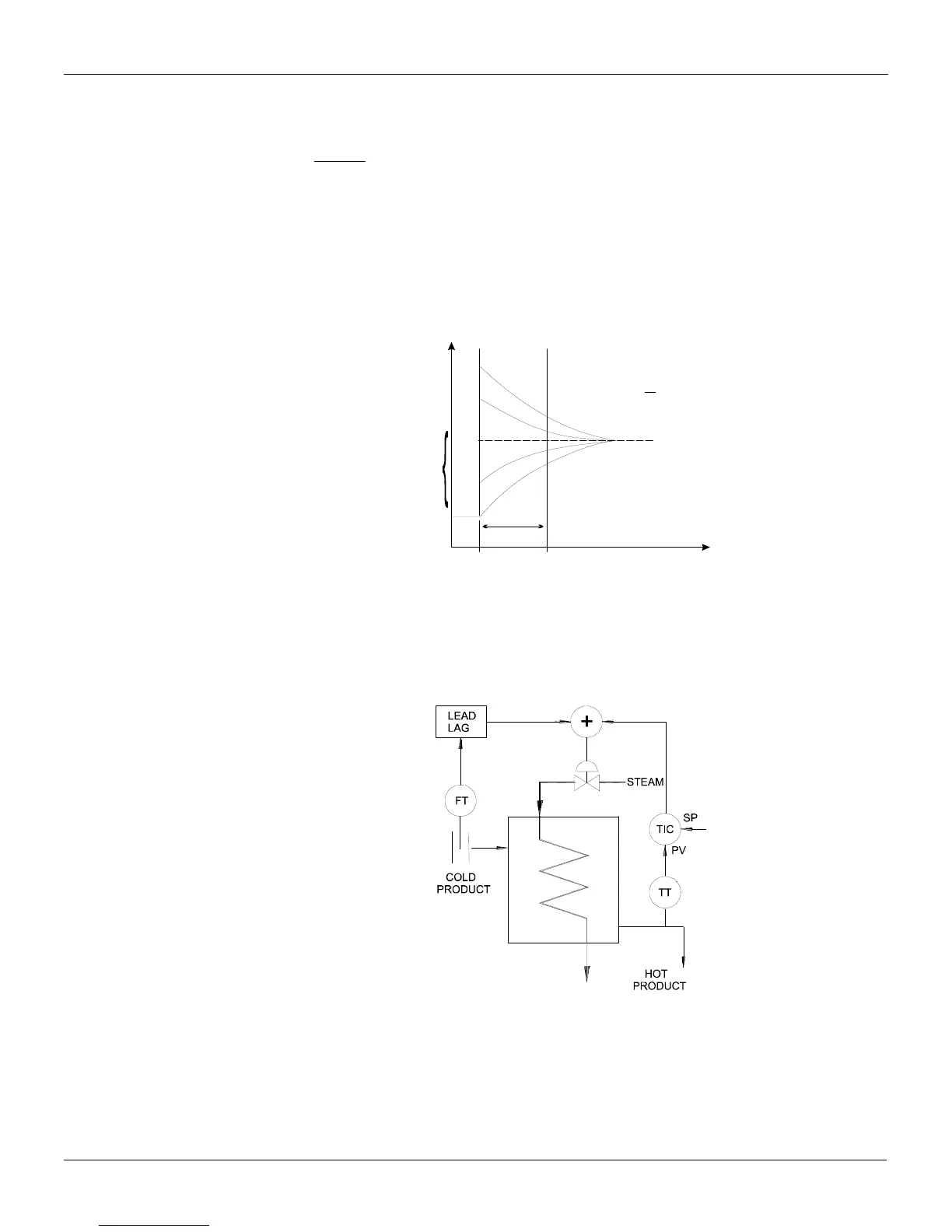
This block is often used in control loops with feedforward control. Its function is to compensate
differences between time constants of the disturbance and the manipulated variable on the controlled
variable. The following figure shows a lead/lag block inse
fl
Fig 4.15.3 - Steam flow rate control loop with Lead-Lag