D: Audio Interfacing
Page 6-16 | Section 6: Appendices C10 HD Installation Manual
'! &$
All analogue audio inputs and outputs are electronically balanced. The screen pins are all directly connected to the chassis
a
t the point of entry to comply with AES/EBU grounding and EMC recommendations.
$'&%
I
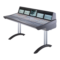
t is strongly recommended that balanced connections are used wherever possible using high quality screened cable. The
following diagram shows the recommended connection with both screens connected to the chassis:
On some older items of equipment the screen connection may still be referenced to the circuit 0V point rather than the
chassis. In these cases it may be advantageous to disconnect the screen at this connection. Note however that this practice
will degrade the EMC performance.
! & &! ' #'" &
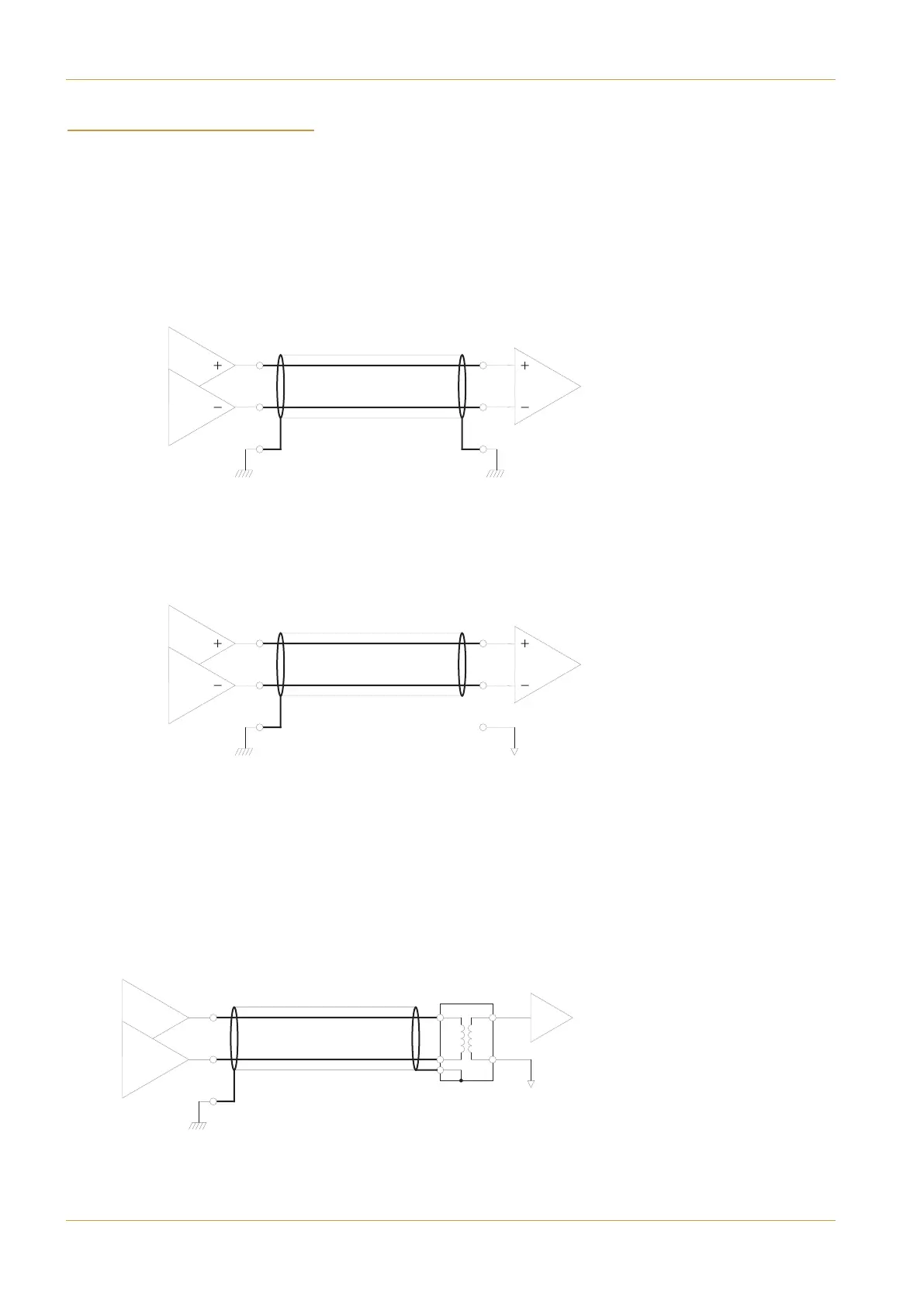
Connecting to unbalanced equipment can be much more problematic. It is quite likely that induced RF earth currents will
become referenced to the audio 0V which will give rise to audible hum and buzz.
The recommendation for connection of balanced to unbalanced equipment is to isolate unbalanced connections by using
a balancing transformer.
Chassis
Chassis
Chassis
0V
Chassis
0V
Balanced – Balanced
Both screens connected to chassis
(Recommended)
Balanced – Balanced
One screen connected to chassis
Balanced – Unbalanced
One screen connected to chassis
(Recommended)