C10 HD Installation Guide Section 4: Configuration | Page 4-27
'($ #")& & -&'
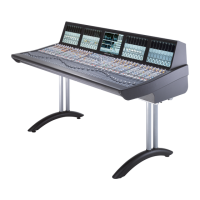
The C10’s fader strips, in both the Channel and Centre Sections, are arranged in Layers, each of which can be brought
onto the physical control surface using softkeys. There are ten Fader Layers available.
E
ach channel can be placed in more than one Layer. For example, any signals that require constant attention might be
placed in the same position within each Layer so that they are always in the same channel strip on the control surface,
regardless of the selected Layer.
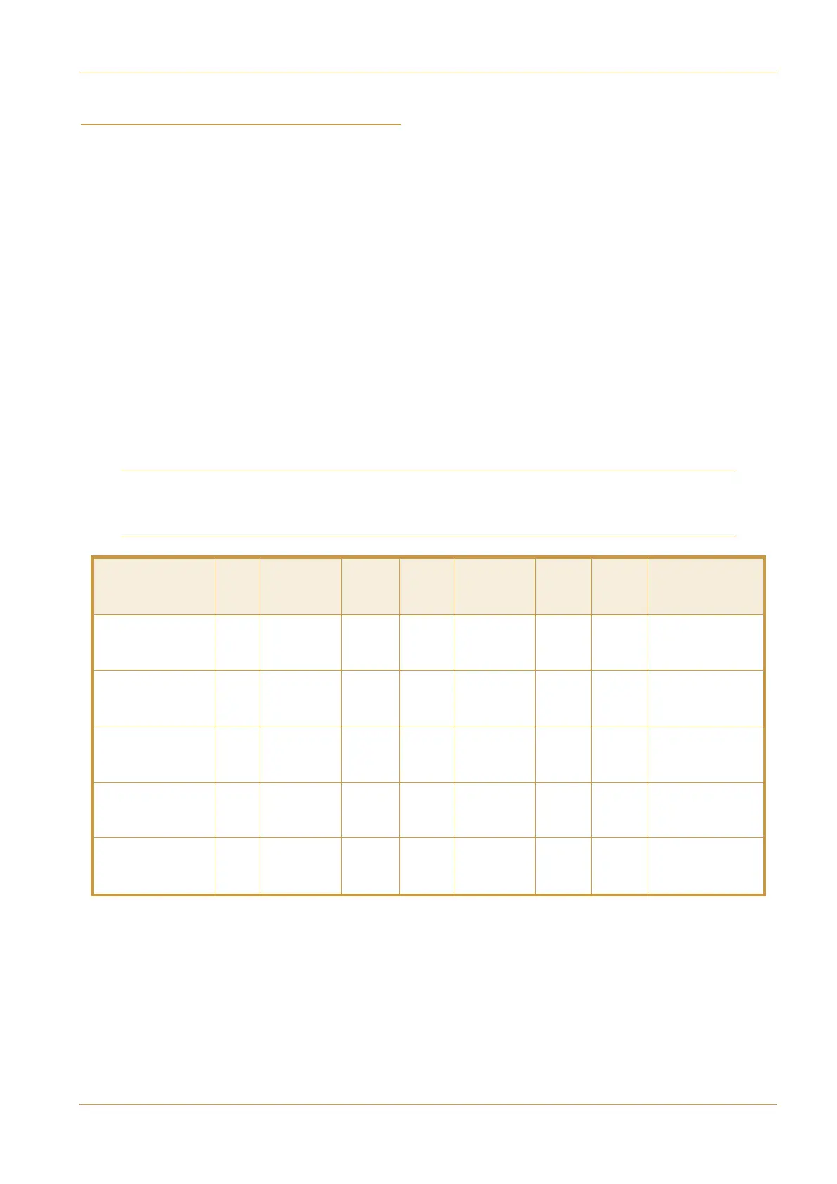
Fader Strips can be any of the following, as explained in the table below:
- Input channels
- ASG (Audio Sub Group) 1 to 8 (for 8 x stereo format) or 1 to 4 (for 2 x 5.1 and 2 x stereo format).
- PGM (Programme) 1 or 2
- DBA (Direct Bus Access) 1 to 16
- Aux busses 1 to 8 (even-numbered busses are locked out when part of a stereo aux)
- Mix Minus busses 1 to 16 (even-numbered busses are locked out when part of a stereo Mix Minus)
- Control Group Master 1 to 16
- DAW Control Channels
Note that some busses, such as ASG busses, can access Master Channel functions and can feed Aux and Mix Minus
busses. To take full advantage of this, assign these busses to full fader strips. Refer to the Operator’s Manual for a full
list of signal path functionality.
'"
/$(
% -"!' "'&( -
),!!
&
#)(
'
&
#)(
$!
&
#)(
#&!('
Input Channel
✔ ✔ ✔ ✔ ✔ ✔ ✔
Mono, Stereo,
5.1, Custom*
Audio Subgroup
(ASG)
✔ ✔ ✔ ✔ ✔
Stereo
5.1
Programme Bus
(PGM)
✔ ✔
Stereo
5.1
Aux /
Mix Minus
✔ ✔
Mono
Stereo
Direct Bus Access
(DBA)
✔ ✔ ✔
Mono
B: Console Configuration