%"!)$ %'""+ $!(
&!
!%
• Posidrive no.1 screwdriver
"$!'$
1. Confirm that both the mains input power cables are disconnected
before attempting to remove the power supply modules.
2. It will be necessary to remove the channel TFT screen panel from the
appropriate bay to gain access to the PSU modules. Refer to page 7-4 for
TFT removal instructions.
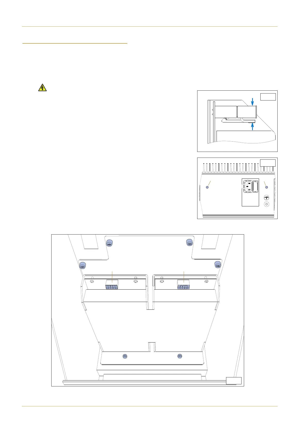
3. Disconnect both power leads (A) indicated in diagram S6-3. Note that the
power connector is secured by a retaining clip on its lower side. To
release the clip squeeze the tab upwards indicated by diagram S6-1.
4. From beneath the console, remove two M3 cross-head screws (B) as
shown in diagram S6-2. NOTE. This step is only required on consoles fitted with
two individual modules mounted in separate console bays.
5. From inside the console, unscrew the six finger-screws indicated by (C) in
diagram S6-3. (Do not use a screwdriver to undo these fasteners).
6. The power supply assembly can now be removed from the console
complete with the heatsink attached. Do not remove the PSU module
from its baseplate.
S6-1
S.6-2
S.6-3
(A)
(C)
(C)
(C)
(C)
(C)
(C)
(B)
(B)
(A)
Page 7-6 | Section 7: Service Information C10 HD Installation Manual
Power Supply