Below each connection in the 8=:)A4 display, there is a ‘light’ which is lit green to indicate that the link is working, a
l
ink number and format, and any link-specific details.
‰ Alpha-Link modules display a single blue box which defines the address for the IO included in them. Stabbing on the
box brings up a calculator pop-up on which the address can be defined.
Note that each device needs to have a unique device number.
Links to other ! units display the IO channels currently assigned to that link – these are automatically assigned by
the console.
Note that on a redundant system, the processors have to be configured independently and must be identical. If the IO
Links page is incorrectly configured on one processor, the redundancy indicator at the top of the Touchscreen will still
display Sync OK.
‰ When using redundant fibre Links to an Alpha-Link LIVE-R the MADI ports will need to be configured as redundant
pairs by stabbing the C0; button. See Section 5-35 for additional details.
$ " #")&(#"
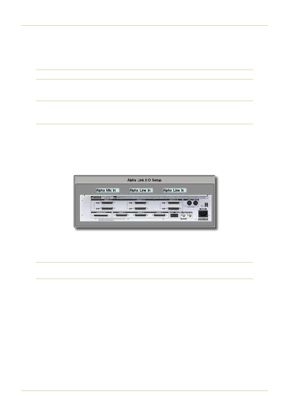
‰ Stabbing on the >=586 button for an Alpha-Link module brings up the ;?70 8=:#'4BC? display, in which
each input to the 8-RMP unit can be selected:
‰ Touch each blue box to switch between ;?70 8=4=and ;?70!82=, then touch outside the display to close
it.
‰ Touch the '0D4button in the 8=:)A4display before touching outside of the display to close it.
If you are configuring links to MORSE stageboxes or B-RIO units, please refer to the Operator’s Manual Section 7 for
additional details.
Page 4-10 | Section 4: Configuration C10 HD Installation Guide
A: IO Configuration