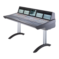
C10 HD Installation Guide Section 4: Configuration | Page 4-19
'($ ( "+ ##")&(#"
We will now run through the basic channel routing and monitoring operations necessary to confirm that the sources are
correctly configured. It will help if you can use a source which is generating a signal that can be auditioned!
''"" "$)( '#)&' (# "" '
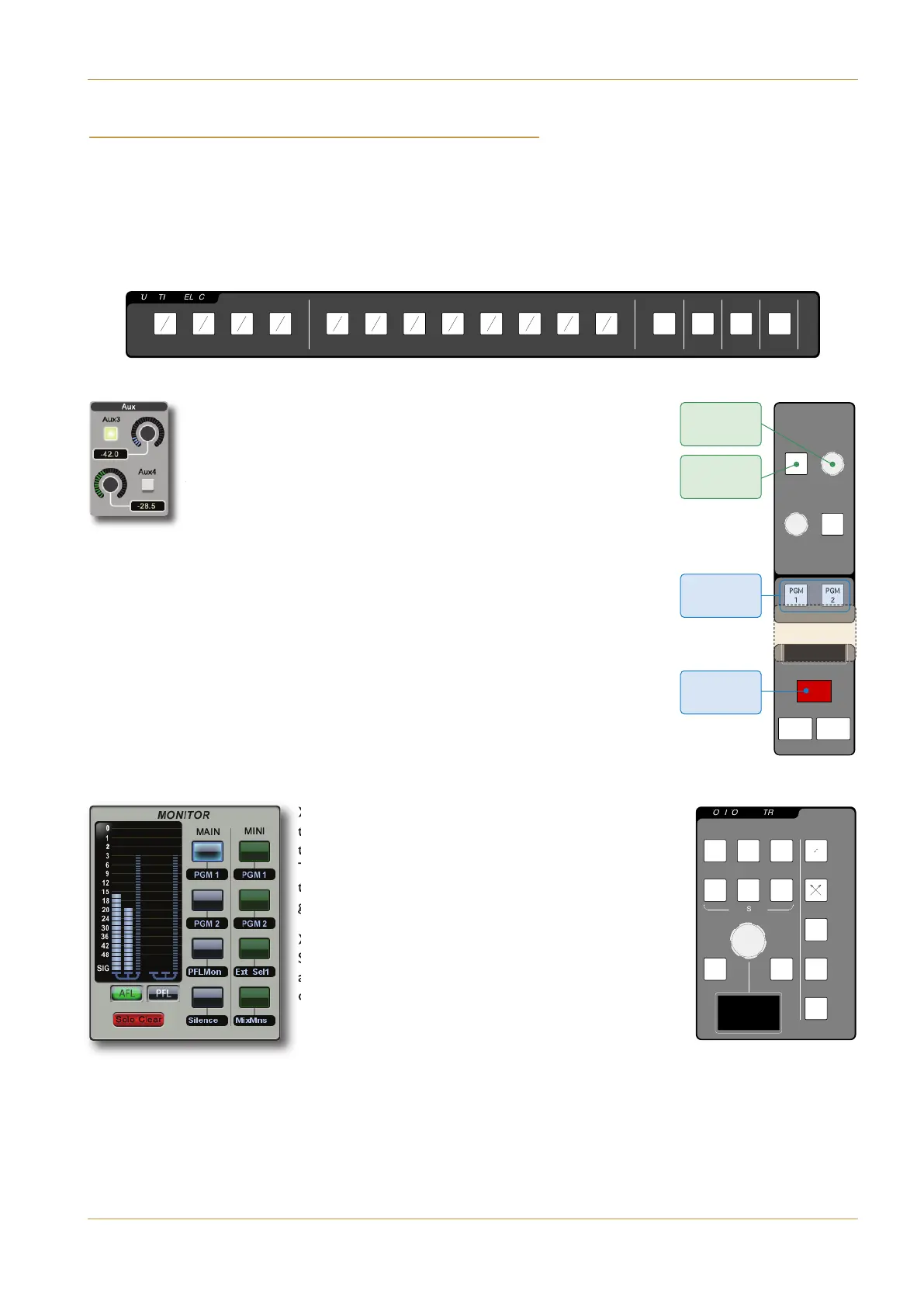
‰ Assign the input routing function to the channel softkeys by pressing the &( button at the right-hand end of the
FUNCTION SELECT panel. The Input and Insert lists will appear in the bottom of the Channel Information Display.
‰ Using the Upper Quik-Knob in any channel, move through the list of
available inputs as (indicated by the source names in the black box to the
right of the Take button) and press the button to its right to ‘Take’ the
input signal (in other words, to assign the selected input to the channel). If
the channel was unformatted, it will now automatically take on the format
(mono, stereo or 5.1) of the input signal.
&#)(" ( "" (# ( $&#&!! )'
‰ Lift the channel fader, and ensure that the channel is ‘on’, as indicated by the #"
button above the fader being lit, and by the presence of the moving meters in the Channel
Information Display above the fader strip.
‰ Press $!, located above the eight numbered buttons in the fader strip, to route
the channel to Programme Bus 1.
)(#"" ( $&#&!! )' #" ( !#"(#&'
‰ In the !#"(#& area of the Touchscreen, touch the
top button in the !" column. This routes the PGM 1 bus
to the main monitors, as indicated by the label beneath it.
The button surround should become blue. Also ensure that
the Solo Clear button below the AFL and PFL buttons is
grey, indicating that no AFLs or PFLs are active.
‰ In the MONITOR CONTROLS area of the Centre
Section, ensure that neither the ! nor )( buttons are
active, and turn up the encoder. The signal selected for the
channel input should now appear on the monitors.
2 ASG 3 ASG 4 ASG 5 ASG 6 ASG 7 ASG 8
4
1 PGM 2
4
1
S
2
4
MONITOR CONTROLS
D
LCR
RSLFELS
DIM CUT
FLIP
MONO
5.1
O
CUT/SOLO
M
R
Monitor Controls
P
GM
1
P
GM
2
1
P
2 ASG 3 ASG 4 ASG 5 ASG 6 ASG 7 ASG 8
4
1 PGM 2
4
1
S
2
4
1
M
2
A 3
A 4
A 5
A 6
A 7
A 8
A
O
o
G
2
2
o
e
5
S
S
R
R
2
6
a
t
N
X
S
T
Y
M
M
M
M
M
M
MGP
1
G
P
2
M
F
F
F
F
O
P
O
4
1
1
1
1
1
1
N
N
M
M
R
8
1
1
1
1
1
1
C
O
1
G
G
M
M
M
M
M
M
M
N
L
N
N
L
N
N
N
N
N
N
N
N
L
0
0
0
0
0
0
0
0
0
0
0
0
0
0
0
0
0
0
0
0
0
0
0
0
0
0
0
0
0
T
T
0
0
0
T
T
0
0
T
Upper
Quik-Knob
Upper
Quik-Key
PGM Routing
Buttons
AFL PFL
ON
9
2 ASG 3 ASG 4 ASG 5 ASG 6 ASG 7 ASG 8
4
1 PGM 2
4
2
4
1
M
2
A 3
A 4
A 5
A 6
A 7
A 8
A
O
o
G
2
2
o
e
5
S
S
R
R
2
6
a
t
N
X
S
T
Y
M
M
M
M
M
M
M
F
F
F
F
O
P
O
4
1
1
1
1
1
1
N
N
M
M
R
8
1
1
1
1
1
1
C
O
1
G
G
M
M
M
M
M
M
M
N
L
N
N
L
N
LLFAFP
O
N
N
N
N
N
N
N
L
0
0
0
0
0
0
0
0
0
0
0
0
0
0
0
0
0
0
0
0
0
0
0
0
0
0
0
0
0
T
T
0
0
0
T
T
0
0
T
Channel On
Button
2 ASG 3 ASG 4 ASG 5 ASG 6 ASG 7 ASG 8
4
1 PGM 2
4
1
S
2
4
FUNCTION SELECT
E
PAN
1
2
3
4
5
6
7
8
I/P O/P RTE
1
2
3
4
5
6
7
8
9
1
0
11
1
2
13
1
4
15
1
6
AUX
R
MIX MINUS
P
O
o
G
2
2
o
e
5
S
S
R
R
2
6
a
t
N
X
O
S
135
2
4
UA
6
71
I
8
2
M
357
4
68
X
8
91113
D
1
012
IMSUNIM
S
13 15
NAP
1
416
T
NP PR/I/O
Y
ETR
M
M
M
M
M
M
M
F
F
F
F
O
P
O
4
1
1
1
1
1
1
N
N
M
M
R
8
1
1
1
1
1
1
C
O
1
G
G
M
M
M
M
M
M
M
N
L
N
N
L
N
N
N
N
N
N
N
N
L
0
0
0
0
0
0
0
0
0
0
0
0
0
0
0
0
0
0
0
0
0
0
0
0
0
0
0
0
0
T
T
0
0
0
T
T
0
0
T
Function Select panel
A: IO Configuration
 Loading...