% &$ &&&!'%$ $!(
&!
!%
• Posidrive no.1 screwdriver
"$!'$
1
. Shutdown and then switch off the console at both power input panels.
Remove both input power leads.
2. Remove the top trim from the console. The trim is secured with a
single cross-head screw (A) in each console bay as shown in diagram
S4-1. Once all the securing screws are removed the top trim can be
pulled upwards at its front edge and removed.
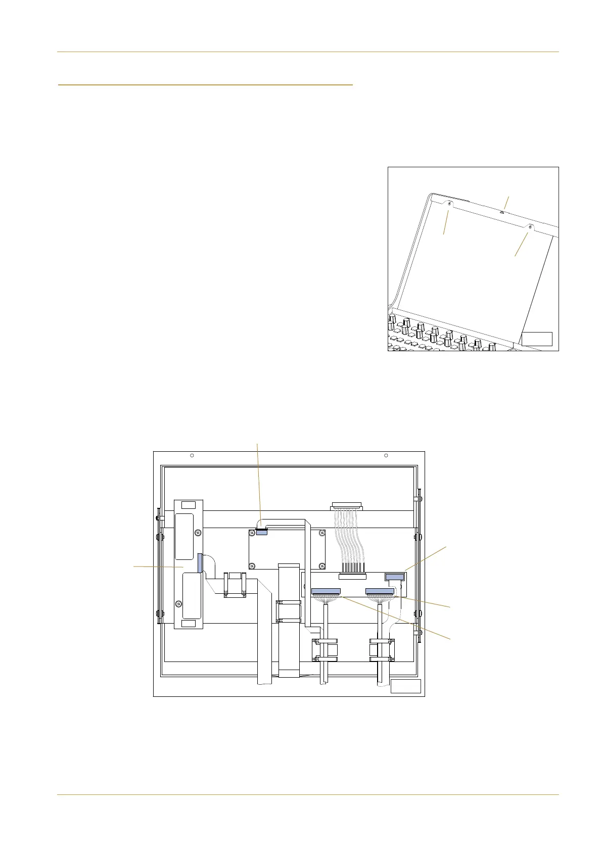
3. Remove the two cross-head screws (B) along the top edge of the TFT
panel as shown in diagram S5-1.
4. Tilt the top edge of the TFT panel towards the front of the console
and then pull upwards to free the bottom edge of the TFT panel.
The bottom edge of the panel is gripped by EMC shielding clips. A gentle side-
to-side motion will assist in freeing the panel in a controlled manner.
5. Remove the five connecting cables as indicated in diagram S5-2.
12W Micro
Backlight power
8W Micro
Touchscreen data
10W Ribbon
Control
20W Micro
‘LVDS IN 1’
20W Micro
‘LVDS IN 2’
(
A)
(B)
(B)
S.5-1
S.5-2
C10 HD Installation Manual Section 7: Service Information | Page 7-5
Centre TFT