(*$
*
)%*)
%
'")'(
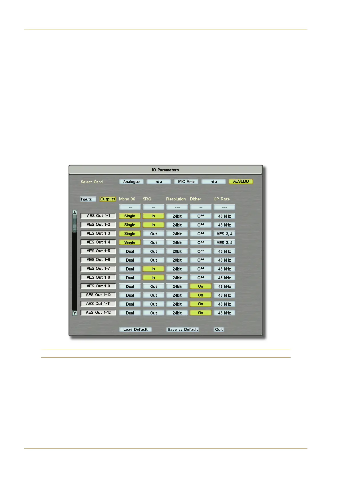
"?>? determines how 96kHz outputs are derived. The options are Single Wire ((9>7) where each channel
uses one output clocked at 96kHz, or Dual Wire (D1<) where each channel using two outputs
c
locked at 48kHz for odd/even samples. However, as 96KHz outputs don’t provide any benefits (see
note above), how they are derived is largely irrelevant!
(' allows sample rate converters to be placed on outputs. If any of the remaining digital output parameters
r
equire SRCs, they are automatically introduced;
'5B?<DC9?> allows the output bit resolution to be altered. Stabbing these buttons calls up a '5B?<DC9?> pop-up
from which 29C, 29C and 29C can be selected;
9C85A switches dither on and off;
$%'1C5 calls up an $DC@DC<?3; pop-up which allows the output sample rate to be set to follow the first
six digital inputs ((, (, (), 44.1kHz (;I), the current console sample
rate (displayed above the option ;I) or twice the current console sample rate (GB).
Note: Digital IO is configured in pairs.
Page 5-34 | Section 5: System Administration C10 HD Installation Manual
Route Menu