SBC Processor
%%"$!%%!$ $!(
&!
!%
• 2mm Hex Driver
• Module Pullers (2)
• No.1 Posidriver
• Small flat-blade screwdriver – for connector (A5)
"$!'$
1. Shutdown and then switch off the console at both power input panels. Remove both input power leads.
2. The SBC control computer is located in the console’s centre section. (Consoles with redundant processing will
have an additional computer assembly located in channel bay 1–8). To gain access to the SBC control computer(s)
it will first be necessary to remove the appropriate channel/centre TFT screen and also the channel/centre control
tile. Refer to sections S.2 – S.5 for TFT and tile removal information.
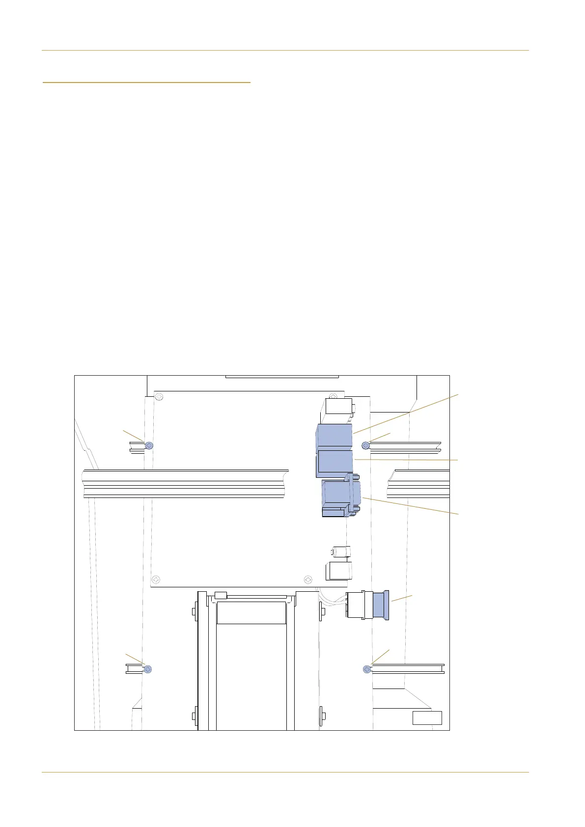
3. Remove the connector (A1) ‘POWER’ as indicated in diagram S8-1.
4. Remove the RJ45 network lead at (A2) ‘IP NET’.
This gives easier access to the four fixing screws (B).
(B)
(B)
(B)
(A1)
‘POWER’
(A2) ‘IP NET’
(A3) ‘ITX 1’
(A4) ‘ITX’
(A5) ‘ITX’
(A6) VGA
(B)
S.8-1
Page 7-8 | Section 7: Service Information C10 HD Installation Manual