$*$% ! %$
$
# * &%
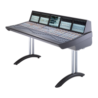
C10HD consoles can be specified with 8, 16, 24, 32 or 40 channel faders plus the 8-fader master section (usually referred
t
o as the centre section). The centre section can be located in any of the console channel bays. Producer’s tables, 19”
racking or corner sections are not available.
The physical size of the console does not limit the number of DSP processing channels available; this is determined solely by
the quantity of DSP resource specified for the processor. Processing is available in quantities of 64, 96, 128 or 160 channels.
All processing functions are internal to the console frame – there are no remote PSU or computer racks to be
accommodated. Input/output is handled by remote I/O units which connect to the console using MADI fibre cables.
%#
The frame is supplied with flat sides to reduce the overall width. Where a console is freestanding contoured side arms
are available to provide a comfortable finish. These arms must be specified at the time of order.
$
Consoles of 16 channels and above are normally supplied with legs as shown opposite. The legs can be removed if the
console is to be used on a table or where it is more convenient to mount the console to a separate chassis – such as in
an OB vehicle. Four threaded inserts are fitted to the base of each channel bay which should be used to secure the console.
Legs are not available for the 8-channel console.
Console fixing inserts are metric M8 standard. Ensure that a minimum of 10mm and a maximum of 25mm thread protrusion
is available to secure the console.
The supporting table must not extend beyond the flat base of the console into the rear connector panel area. Doing so
would not allow sufficient space for the fibre cables to exit without excessive bending strain and possible risk of fracture.
Refer to Appendix F for additional details of how to table mount the console.
! (# $&!!$ $ % # $(%$
The console includes double power supplies, either of which is capable of powering the console thus providing power
redundancy. All PSU units are autoranging; mains inputs are accessed via a standard IEC male connectors.
The location of the power supplies in the frame is dependant upon the console frame
size – see page 2-14 for bay layout drawings. The PSU frame section is fitted with
individual isolator switches for each console channel bay plus the processor card(s).
%$ #
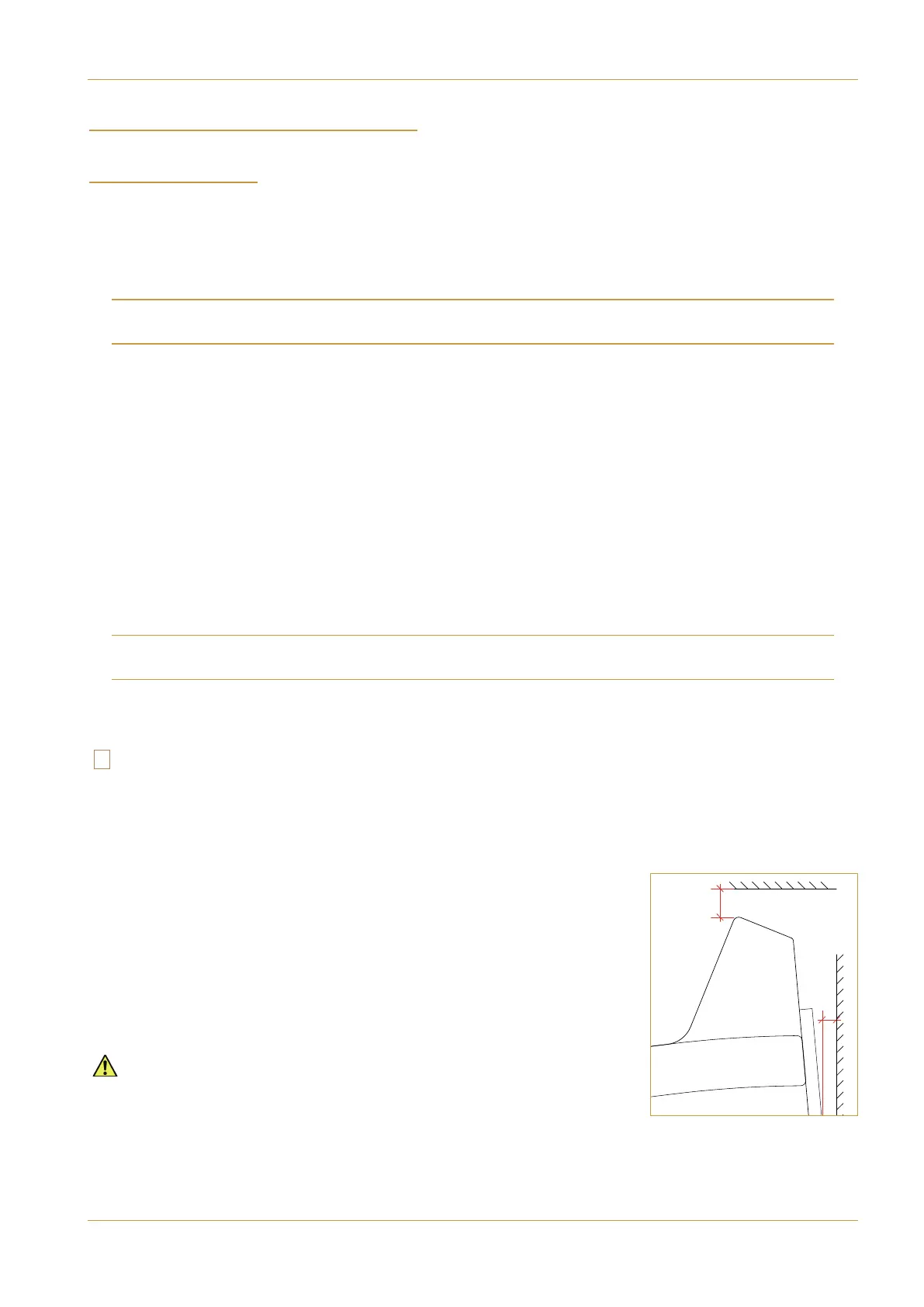
The rear panels of PSU and DSP channel bays are fitted with protruding heatsinks so
care must be taken when planning the installation of studio furniture – such as
shelving – across the rear of the console. Sufficient space must be left to allow the
free flow of air from the rear grills and above the heatsink fins.
Clearance behind the console must not be less than 25mm and clearance above
the console not less than 50mm.
>89+242543+398
389'11'9/43'3:'1 +)9/437+5'7'9/43? '-+
>89+242543+398
Minimum Heatsink Clearances