% #$
!
"
!"!
XLR-3 male
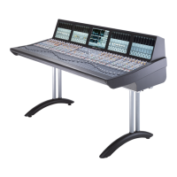
The centre control tile of the console is fitted with a talkback microphone. The output signal is balanced analogue at
approximately 0dBu. Page 3-19.
"! XLR-3 female
Connector wired to a 1/4” stereo Jack socket fitted under the left hand end of the console’s front buffer. This is a wired
c
onnection only; the console is not fitted with any amplification or a level control. Page 3-21.
"!
D25 male "
!"!
D25 female
12 circuits of GP input and output. Inputs are opto-isolated voltage triggered, outputs are via DIL relay. Outputs can be
configured to be either momentary or latching. Page 3-17.
!
D9 male
Two 9-pin serial ports are available for the connection of 3rd party equipment to provide router naming and automation
control. Automatic control backup will be included on systems that are equipped with processor redundancy. Allocation
of function is setup in system software. Page 3-23.
!$ ! RJ45
SSL Net 1&2 – Must always be linked to connect the DSP processor to the internal SSL network. Page 3-5.
SSL Net 3 – Available for the connection of the optional MORSE router or remote GP IO units. Note that it will
be necessary to supply an external Ethernet hub/switch if multiple units are to be connected.
TCP/IP – Must be connected to a PC via the facility’s Ethernet network. Page 3-5.
!" USB
Available for the connection of an external keyboard/trackball for text input as an alternative to the touchscreen. A
suitable combined keyboard/trackball is available to order as an option.
@ #" HD15F USB
Direct keyboard and monitor connections to the SBC Linux PC. A permanent connection is not required – these ports
are available for access during initial system configuration where no network computer is available.
LC Fibre
Fibre interface ports for the connection of remote I/O units. Four ports are supplied as standard – each fitted with a
multimode duplex LC fibre interface adapter. A second four port card can be specified (as shown opposite) to provide
additional I/O capacity. Page 2-10, 3-11.
RJ45
Direct network connection to facilitate communication with a suitably equipped DAW. Page 3-25.
& BNC
Input for system reference. A sync reference common to all equipment will be required if using digital peripherals. The
input is not internally terminated and must be fitted with the external tee-piece and terminator provided. Two sync cables
will be required for redundant processor systems – sync must not be daisy-chained between units.
!
" # "! D9 female
Video output of the centre section touchscreen. Can be connected to an external XGA monitor for backup or training
purposes – note that the display is in portrait orientation. Page 3-23.
#
"!"! D9 female
Used only to power the optional SSL relay fibre-changeover switch. Do not use for any other function. Not fitted to the
16-channel frame or to consoles without processor redundancy.
1
2
3
4
5
6
7
8
9
10
11
12
>89+242543+398
389'11'9/43'3:'1 +)9/437+5'7'9/43? '-+