)'#) %()*%
All of the tiles on the C10 control surface are connected to the console processor via Ethernet, and the C85A>5C%
(5CD@ section of the A?>C%1>5< menu manages these connections. You will only need to access this section if any
part of your front panel has been changed or stops working properly. We recommend that you do not alter any of the
settings in these submenus without close consultation with your local SSL Service representative.
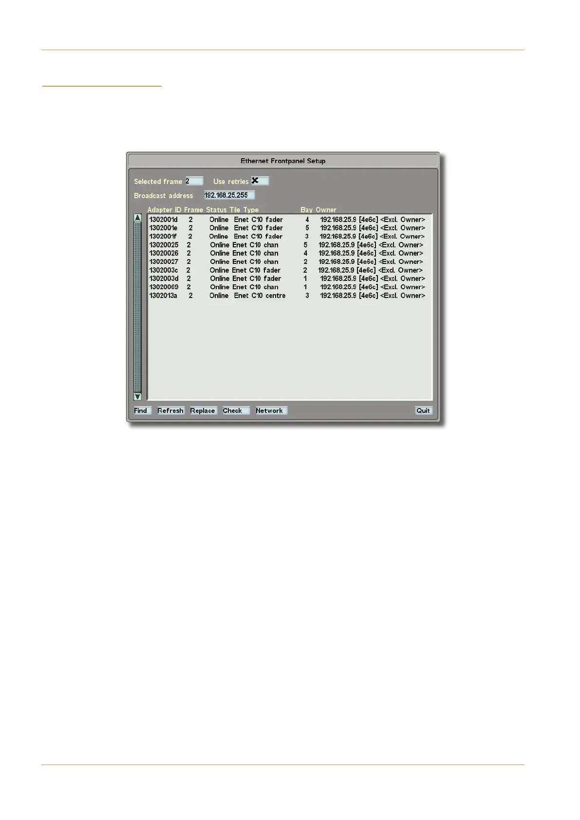
The main part of the C85A>5C%(5CD@ screen consists of a list of each tile in this frame, and the columns contain
the following information:
- 41@C5A is the tile’s unique ID which is the same as that printed underneath the tile.
- A1=5 is the frame number which has been defined in the Enter Frame ID pop-up described below.
- (C1CDB shows whether the tile is online or offline.
- )9<5)H@5 displays what type this tile is:
Centre Section (‘35>CA5’),
Fader (‘6145A’),
Master Channel (‘21H’)
Channel Strip (‘381>’).
- 1H identifies which bay of the frame the tile is located in, and is detected automatically.
- $F>5A displays the IP address of the parent CPU, along with its serial number in brackets, and the state of the
connection (4 meaning good!)
The text for working tiles will be black, whereas the text for any tiles which can no longer be found will be red.
Page 5-52 | Section 5: System Administration C10 HD Installation Manual
Front Panel Menu