%$ " $!(
A
pplies to channel and centre section fader panels.
&!!%
• 2mm Hex Driver
•
Module Pullers (2)
"$
!'$
1. Shutdown and then switch off the console at both power input
panels. Remove both input power leads.
2. Remove the three 2mm hex screws at the front edge of the
fader panel. Screw the module pullers into the two outer holes.
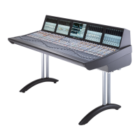
3. Slowly lift the front edge of the fader panel upwards until the
fader motors are visible and are just clear of the front supporting
rail in the console. Refer to diagram S1-1.
The rear edge of the fader panel sits in a slot and will need to
pull forward by approximately 5mm before the panel can be
raised.
4. Tilt the panel upwards at the front until the panel sits vertically
on its rear edge. Refer to diagram S1-2.
The connecting cables will prevent the panel from being lifted out of
the frame at this stage.
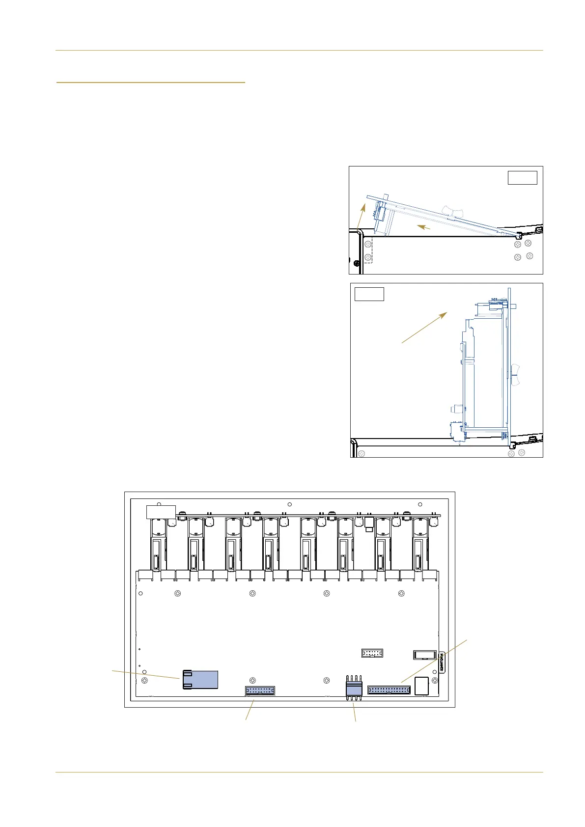
5. Remove the four connecting cables at the lower rear edge of the
panel as indicated in diagram S1-3.
16W Ribbon
Data
4W Molex
POWER
RJ45
Network
26W Ribbon
Data + Power
S.1-1
S.1-2
S.1-3
C10 HD Installation Manual Section 7: Service Information | Page 7-1
Fader Panel