%%""$!%%!$ $!(
&!
!%
• Posidrive no.1 screwdriver
"$!'$
1
. Shutdown and then switch off the console at both power input panels. Remove both input power leads.
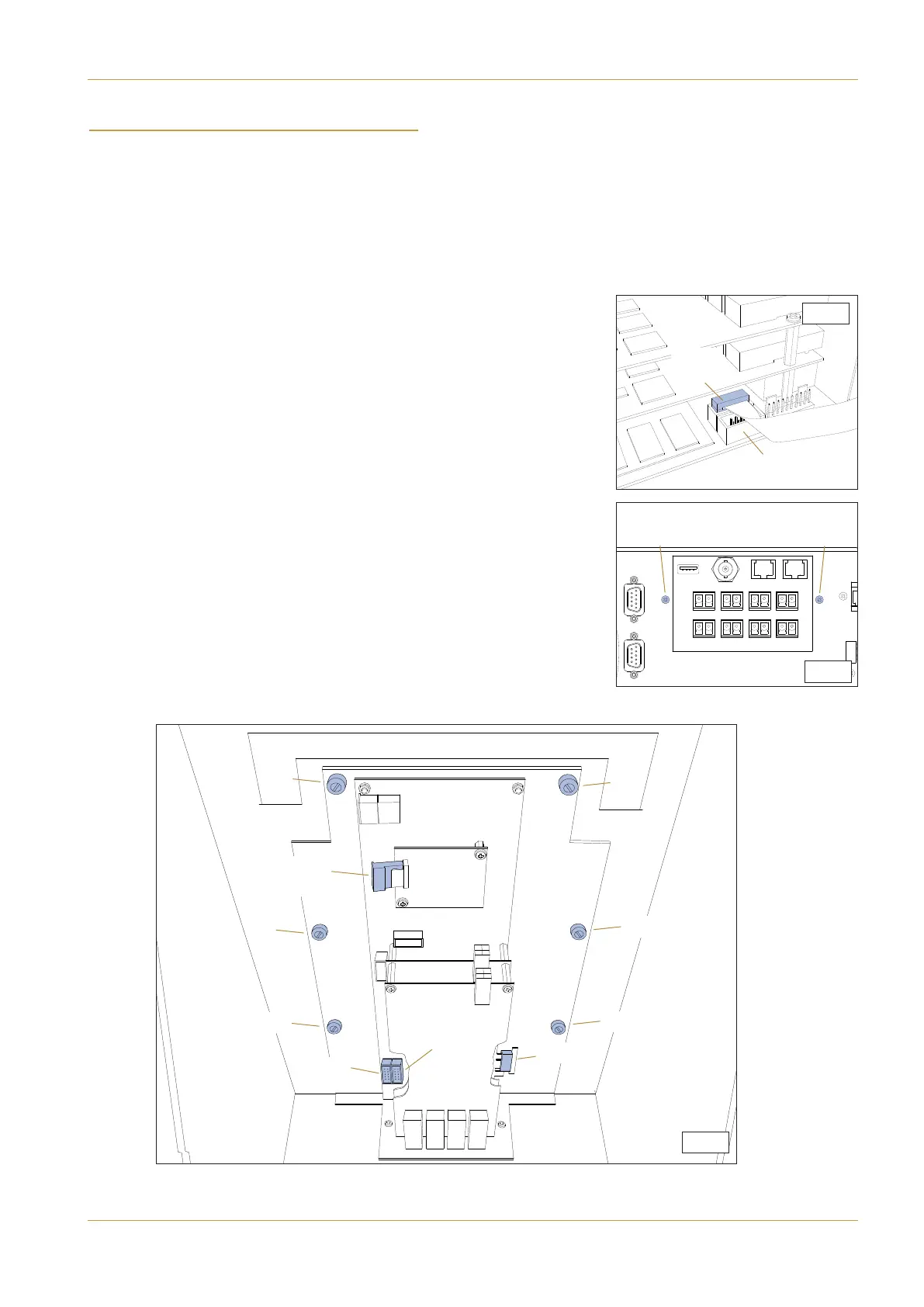
2. The DSP processor module is located behind the TFT touchscreen in the
console’s centre section. (Consoles with redundant processing will have an
additional DSP processor assembly located in the first channel bay).
3. Remove the channel TFT screen panel from the appropriate console
bay(s). Refer to the previous pages for TFT removal instructions.
4. Disconnect the leads: (A1) ‘POWER’, (A2) data lead and (A4) ‘UART 2’ as
shown in diagram S7-3.
Note that the connector (A3) ‘UART 1’ is difficult to remove at this stage as it is
covered by the lower MADI PCB. It is easier to remove after the DSP assembly is
lifted from the backpanel. See diagram S7-1.
5. From beneath the console, remove two M3 cross-head screws (B) as
shown in diagram S7-2.
6. From inside the console, unscrew the six finger-screws indicated by (C) in
diagram S7-3. (Do not use a screwdriver to undo these fasteners).
7. Lift the assembly upwards until connector (A3) can more easily be
removed. The DSP assembly can now be removed from the console.
S.7-3
(A1)
‘POWER’
(A2)
(C)
(C)
(C)
(C)
(C)
(C)
S.7-2
(B)
(B)
S.7-1
(
A3)
‘UART 1’
(A3)
‘UART 1’
(A4)
‘UART 2’
(A4)
‘UART 2’
C10 HD Installation Manual Section 7: Service Information | Page 7-7
DSP Processor