SBC Processor
5. From inside the console, remove four off M3 cross-head screws (B) as shown in diagram S8-1.
6. The ITX computer assembly can now be slid forwards to gain easier access to the remaining connectors at positions
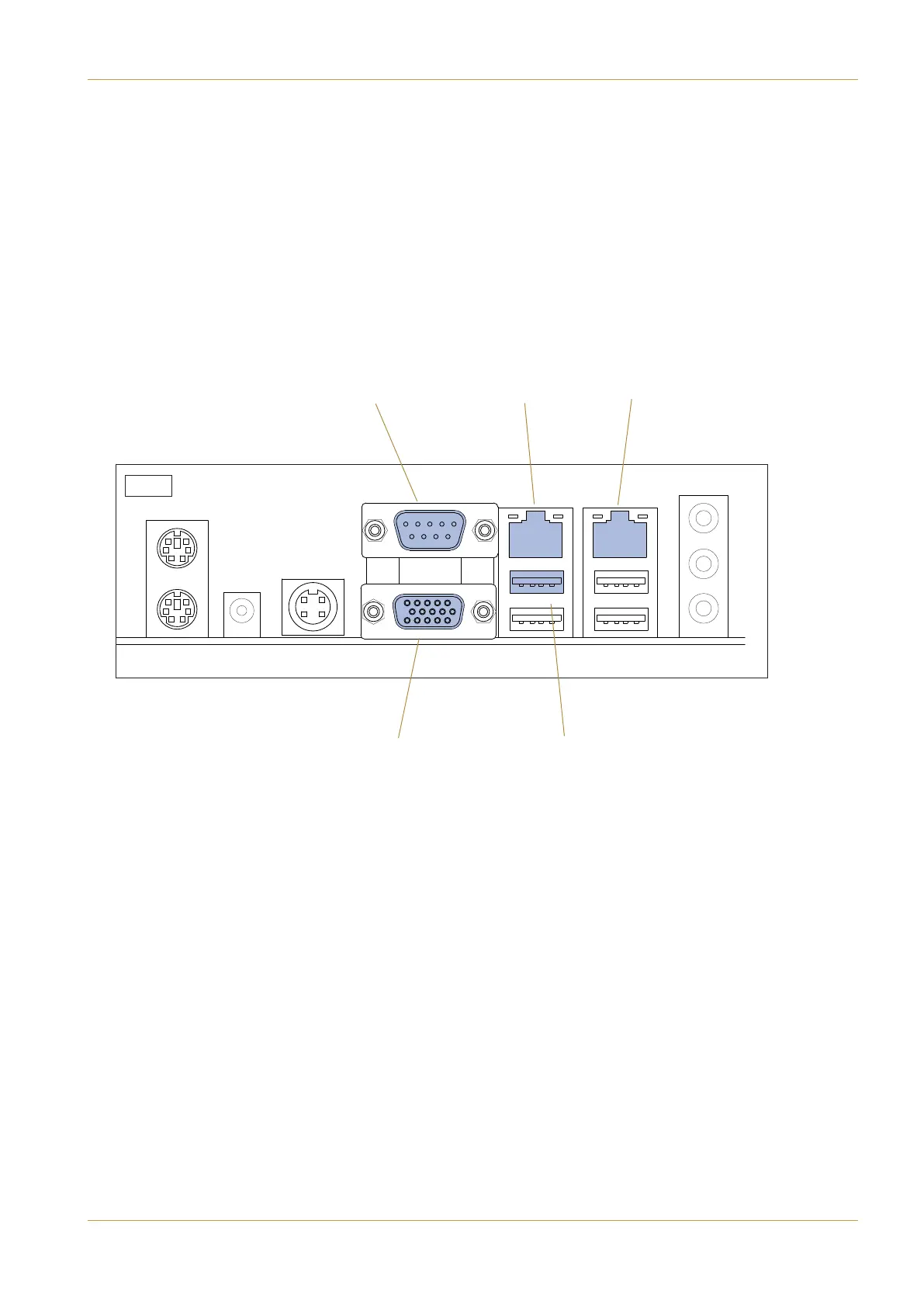
(A3) to (A6). The diagram S8-2 shows the locations of the connectors.
It is not necessary to remove any other connectors from the SBC assembly.
(A5) D9 Female
‘ITX’
(A3) RJ45
‘ITX 1’
(A2) RJ45
‘IP NET’
(A6) HD15
XGA
(A4) USB
‘ITX’
S.8-2
C10 HD Installation Manual Section 7: Service Information | Page 7-9