Determining device type
The semiconductor conductivity type (p or n dopant ions) can be determined from the relative shape
of the C-V curves (see Analysis methods (on page 6-45)). The high-frequency curve gives a better
indication than the quasistatic curve because of its highly asymmetrical nature. Note that the C-V
curve moves from the accumulation to the inversion region as gate voltage, V
GS
, becomes more
positive for p-type materials, but the curve moves from accumulation to inversion as V
GS
becomes
more negative with n-type materials (Nicollian and Brews 372-374).
• If C
H
is greater when V
GS
is negative than V
GS
when poitive, the substrate material is p-type.
• If C
H
is greater with positive V
GS
than negative V
GS
, the substrate is n-type.
• The end of the curve where C
H
is greater is the accumulation region, while the opposite end of
the curve is the inversion.
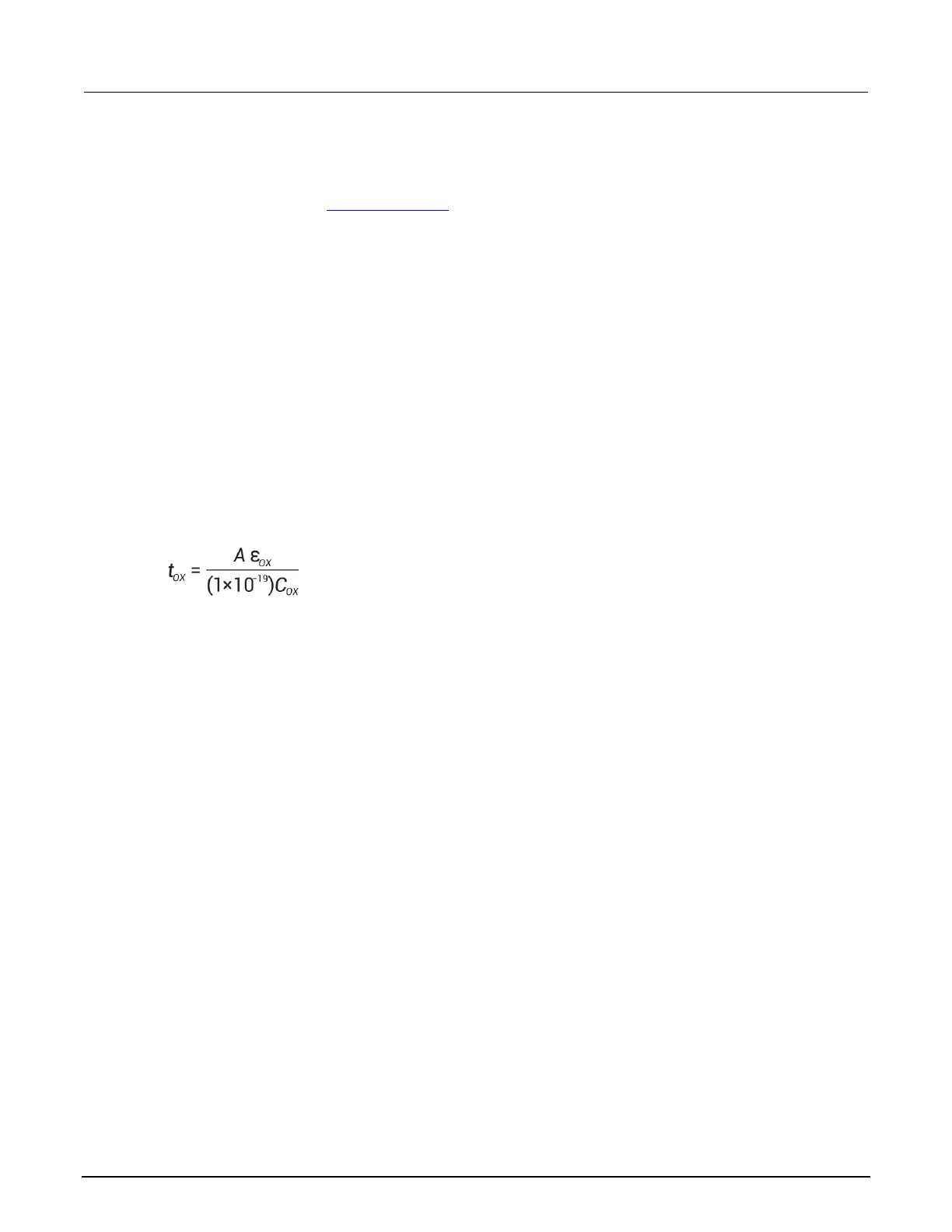
Oxide capacitance, thickness and gate area
The oxide capacitance, C
OX
, is the high-frequency capacitance with the device biased in strong
accumulation. Oxide thickness is calculated from C
OX
and gate area as follows:
Where:
• t
ox
= oxide thickness (nm)
• A = gate area (cm
2
)
•
ox
= permittivity of oxide material (F/cm)
• C
ox
= oxide capacitance (pF)
You can rearrange the above equation to calculate gate area if the oxide thickness is known. Note
that
OX
and other constants are initialized for use with silicon substrate, silicondioxide insulator, and
aluminum gate material, but may be changed for other materials.
Series resistance
The series resistance, R
SERIES
, is an error term that can cause measurement and analysis errors
unless this series resistance error factor is taken into account. Without series compensation,
capacitance can be lower than normal, and C-V curves can be distorted. The software compensates
for series resistance using the simplified three-element model shown in the simplified model below. In
this model, C
OX
is the oxide capacitance. CA is the capacitance of the accumulation layer. The series
resistance is represented by R
SERIES
.
 Loading...


