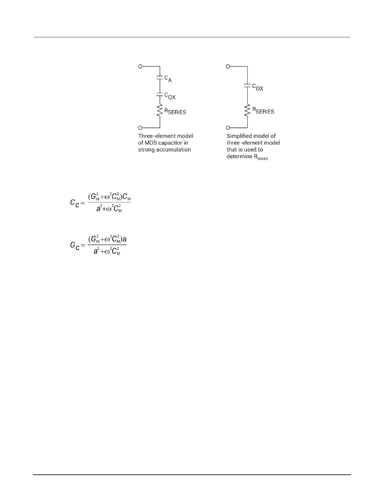
Figure 112: Simplified model to determine series resistance
From Nicollian and Brews 224, the correction capacitance, C
C
, and corrected conductance, G
C
, are
calculated as follows:
and:
Where:
• a = G
M
- (G
2
M
+
2
C
2
M
) R
SERIES
• C
C
= series resistance compensated parallel model capacitance
• C
M
= measured parallel model capacitance
• G
C
= series resistance compensated conductance
• G
M
= measured conductance
• R
SERIES
= series resistance
Gain and offset
Gain and offset can be applied to C
Q
and C
H
data to allow for curve alignment or to compensate for
measurement errors. A gain factor is a multiplier that is applied to all elements of C
Q
or C
H
array data
before plotting or graphics array calculation. Offset is a constant value added to or subtracted from all
C
Q
and C
H
data before plotting or array calculation.
For example, assume that you compare the C
Q
and Cn values at reading #3, and you find that C
Q
is
2.3 pF less than Cn. If you then add an offset of +2.3 pF to C
Q
, the C
Q
and C
H
values at reading #3
will then be the same, and the C
Q
and C
H
curves will be aligned at that point.
Gain and offset values do not affect raw C
Q
and C
H
values stored in the data file, but the gain and
offset values are stored in the data file so compensated curves can be regenerated at a later date.

 Loading...


