Model 100E Instruction Manual Instrument Maintenance
045150102 Rev XB1 157
9.2. Predictive Diagnostics
The analyzer’s test functions can be used to predict failures by looking at trends in their
values. Initially it may be useful to compare the state of these test functions to the
values measured on your instrument at the factory and recorded on the M100E Final Test
and Validation Data Form (T-API part number 04551, attached to the manual). Table 9-2
can be used as a basis for taking action as these values change with time. The internal
data acquisition system (iDAS) is a convenient way to record and track these changes.
APICOM control software can be used to download and review these data even from
remote locations (Section 6.11.5. describes APICOM).
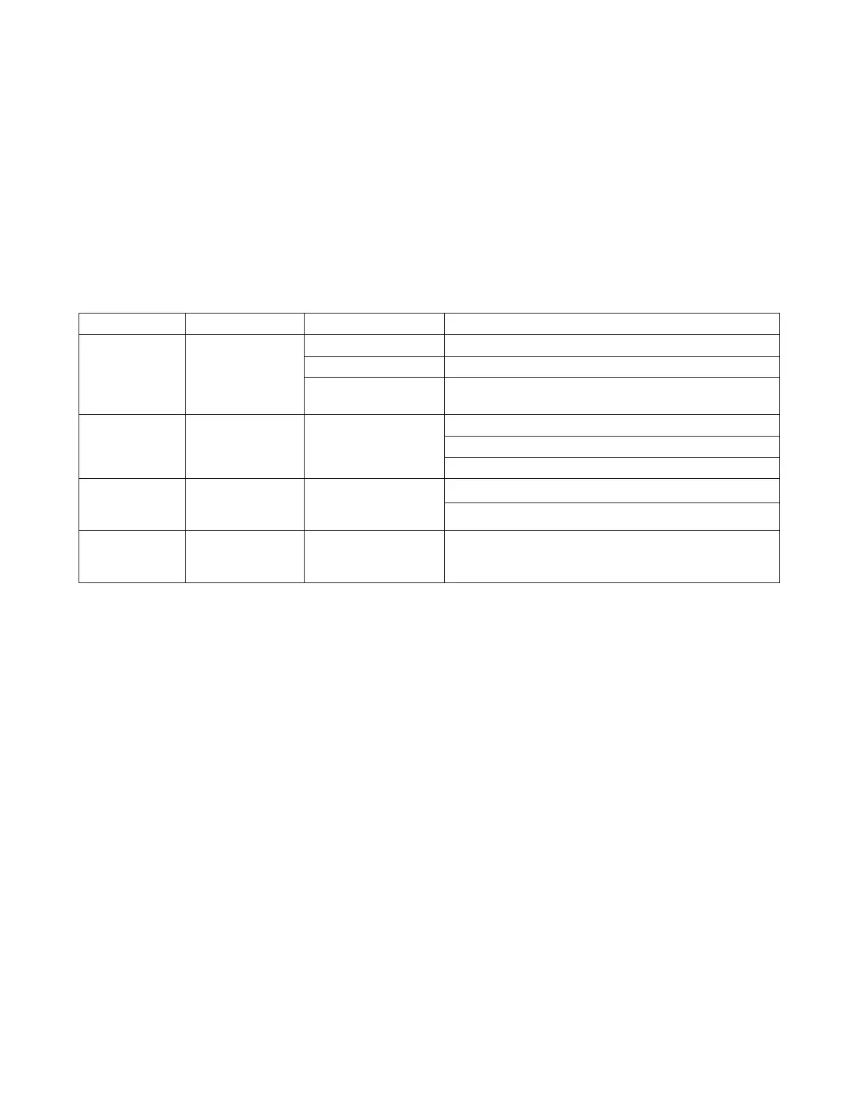
Table 9-2: Predictive Uses for Test Functions
Function Expected Actual Interpretation
Fluctuating Developing leak in pneumatic system
Slowly increasing Flow path is clogging up. Replace orifice filters
SAMPLE
pressure
Constant within
atmospheric
changes
Slowly decreasing
Developing leak in pneumatic system to vacuum
(developing valve failure)
Scrubber material exhausted
PMT cooler failure
DRKPMT
Constant within
±20 of check-
out value
Significantly
increasing
Developing light leak
Change in instrument response
SO
2
CONC
(IZS) at span
Constant
response from
day to day
Decreasing over
time
Degradation of IZS permeation tube
SO
2
CONC at
span
Constant for
constant
concentration
Decreasing over
time
Drift of instrument response; UV Lamp output is
excessively low; clean RCEL window
9.3. Maintenance Procedures
The following procedures need to be performed regularly as part of the standard
maintenance of the Model 100E.
9.3.1. Changing the Sample Particulate Filter
The particulate filter should be inspected often for signs of plugging or excess dirt. It
should be replaced according to the service interval in Table 9-1 even without obvious
signs of dirt. Filters with 1 and 5 µm pore size can clog up while retaining a clean look.
We recommend handling the filter and the wetted surfaces of the filter housing with
gloves and tweezers. Do not touch any part of the housing, filter element, PTFE retaining
ring, glass cover and the O-ring with bare hands.
To change the filter according to the service interval in Table 9-1:
Turn OFF the analyzer to prevent drawing debris into the sample line.
Open the M100E’s hinged front panel and unscrew the knurled retaining ring of the filter
assembly.