Model 100E Instruction Manual TROUBLESHOOTING & REPAIR
045150102 Rev XB1 203
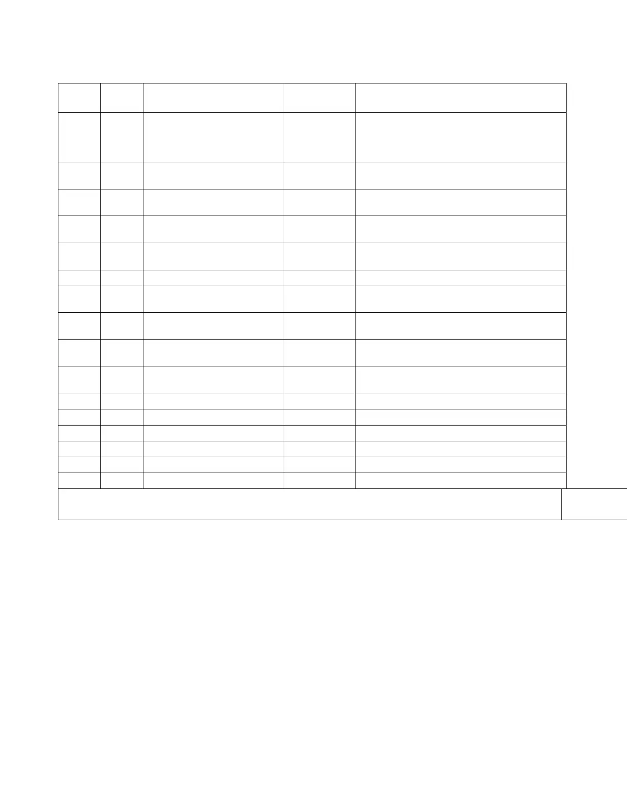
Table 11-2: Relay Board Status LEDs
LED Color FUNCTION
FAULT
STATUS
INDICATED FAILURE(S)
D1 red Watchdog Circuit; I
2
C bus
operation.
Continuously
ON or OFF
Failed or halted CPU; faulty motherboard,
keyboard, relay board; wiring between
motherboard, keyboard or relay board; +5
V power supply.
D2
yellow Relay 0 - sample chamber
heater
Continuously
ON or OFF
Heater broken, thermistor broken
D3 yellow Relay 1 – SO
2
converter
heater
Continuously
ON or OFF
Heater broken, thermocouple broken
D4
1
yellow Relay 2 - manifold heater Continuously
ON or OFF
Heater broken, thermistor broken
D5 yellow Relay 3 - IZS heater Continuously
ON or OFF
Heater broken, thermistor broken
D6 yellow Relay 4 - Spare N/A N/A
D7
2
green Valve 0 - zero/span valve
status
Continuously
ON or OFF
Valve broken or stuck, valve driver chip
broken
D8
2
green Valve 1 - sample/cal valve
status
Continuously
ON or OFF
Valve broken or stuck, valve driver chip
broken
D9
green Valve 2 - auto-zero valve
status
Continuously
ON or OFF
Valve broken or stuck, valve driver chip
broken
D10 green Valve 3 - SO/SO
x
valve
status
Continuously
ON or OFF
Valve broken or stuck, valve driver chip
broken
D11 green Valve 4 - Spare N/A N/A
D12 green Valve 5 - Spare N/A N/A
D13 green Valve 6 - Spare N/A N/A
D14 green Valve 7 - Spare N/A N/A
D15 green Mosfet1-Unused N/A N/A
D16 Green Mosfet2-Unused N/A N/A
1
Special configurations only
2
Only active for instruments with Z/S valve or IZS options installed
11.2. Gas Flow Problems
The standard M100E has one main flow path. With the IZS option installed, there is a
second flow path flow path through the IZS oven that runs whenever the IZS is on
standby to purge SO
2
from the oven chamber. The IZS flow is not measured and is not
available from the front panel. The full flow diagrams of the standard configuration
(Figure 3-10) and with options installed (Figure 5-2 and 5-3) help in trouble-shooting
flow problems. In general, flow problems can be divided into three categories:
• Flow is too high
• Flow is greater than zero, but is too low, and/or unstable
• Flow is zero (no flow)