Model 100E Instruction Manual Operating Instructions
045150102 Rev XB1 77
The following DC current output limits apply to the current loop modules:
Table 6-9: Analog Output Current Loop Range
Range Minimum Output Maximum Output
0-20 mA 0 mA 20 mA
These are the physical limits of the current loop modules, typical
applications use 2-20 or 4-20 mA for the lower and upper limits.
Please specify desired range when ordering this option.
The default offset for all ranges is 0 mA.
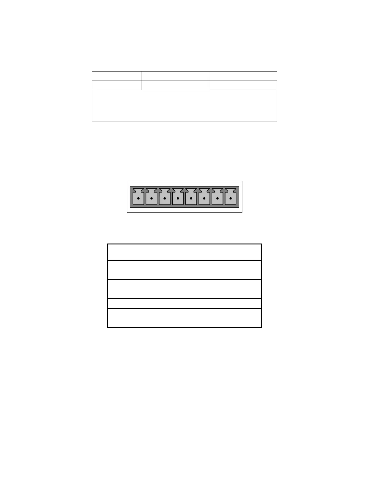
Pin assignments for the output connector at the rear panel of the instrument are shown
in Table 6-10.
ANALOG OUT
A1 A2 A3 A4
+ - + - + - + -
Table 6-10: Analog Output Pin Assignments
Pin Analog
output
VOLTAGE
Signal
CURRENT
Signal
1 V Out I Out +
2
A1
Ground I Out -
3 V Out I Out +
4
A2
Ground I Out -
5 A3 Not Used Not Used
7 V Out not available
8
A4
Ground not available
See Figure 3-2 for a the location of the analog output connector on the instruments rear
panel.