Model 100E Instruction Manual TROUBLESHOOTING & REPAIR
045150102 Rev XB1 201
11.1.4. Status LEDs
Several color-coded, light-emitting diodes (LEDs) are located inside the instrument to
determine if the analyzer’s CPU, I
2
C communications bus and relay board are functioning
properly.
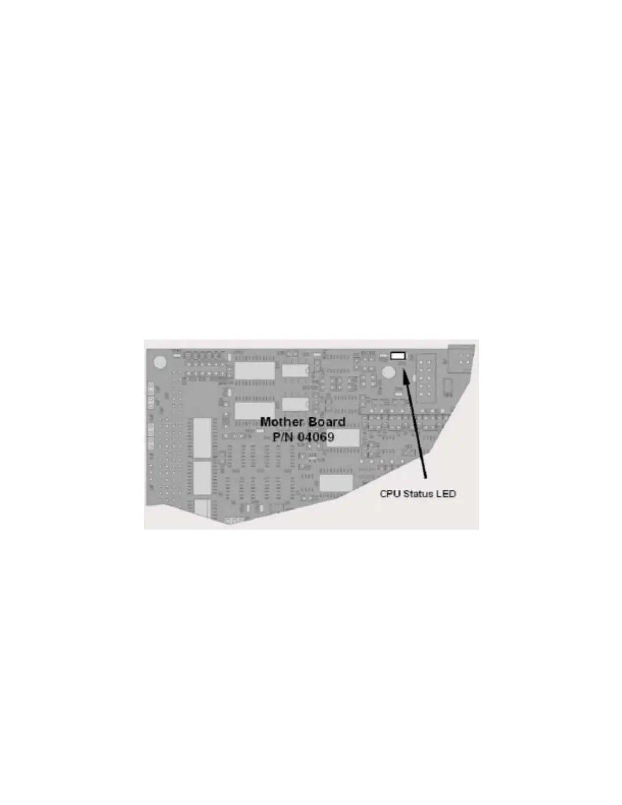
11.1.4.1. Motherboard Status Indicator (Watchdog)
DS5, a red LED on the upper portion of the motherboard, just to the right of the CPU
board, flashes when the CPU is running the main program. After power-up, DS5 should
flash on and off about once per second. If characters are written to the front panel
display but DS5 does not flash then the program files have become corrupted. Contact
customer service because it may be possible to recover operation of the analyzer. If, 30 -
60 seconds after a restart, DS5 is not flashing and no characters have been written to
the front panel display, the firmware may be corrupted or the CPU may be defective. If
DS5 is permanently off or permanently on, the CPU board is likely locked up and the
analyzer should not respond (either with locked-up or dark front panel).
Figure 11-3: CPU Status Indicator
11.1.4.2. CPU Status Indicator
The CPU board has two red LEDs. LED1 is the upper-most LED and is a +5V power
indicator, so it should always be on. However, both CPU LEDs only indicate if the CPU is
powered up properly and generally working. The lower LED will sometimes be stable, and
sometimes will blink. It can continue to blink even if the CPU or firmware are locked up,
and is not an effective indicator for debugging system problems.
11.1.4.3. Relay Board Status LEDs
The most important status LED on the relay board is the red I
2
C Bus watch-dog LED,
labeled D1 (or W/D), which indicates the health of the I
2
C communications bus. This LED