Model 100E Instruction Manual Operating Instructions
045150102 Rev XB1 99
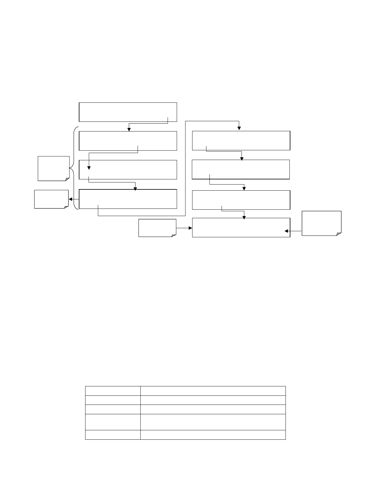
6.9.8. COM Port Testing
The serial ports can be tested for correct connection and output in the COMM menu. This
test sends a string of 256 ‘w’ characters to the selected COM port. While the test is
running, the red LED on the rear panel of the analyzer should flicker.
To initiate the test press the following key sequence.
Select which
COM port to
test.
SETUP X.X
PRIMARY SETUP MENU
CFG DAS RNGE PASS CLK
MORE
EXIT
SETUP X.X
SECONDARY SETUP MENU
COMM
VARS DIAG EXIT
SAMPLE* RANGE = 500.000 PPB SO2 =X.XXX
< TST TST > CAL
SETUP
SETUP X.X
COMMUNICATIONS MENU
ID
COM1
COM2
EXIT
EXIT returns
to the
previous
menu
SETUP X.X
COM1 : TEST PORT
<SET
TEST
EXIT
SETUP X.X
TRANSMITTING TO COM1
<SET
TEST
EXIT
SETUP X.X
COM1 MODE:0
SET>
EDIT EXIT
SETUP X.X COM1 BAUD RATE:19200
<SET
SET>
EDIT
EXIT
EXIT returns to
COMM menu
Test runs
automatically
6.9.9. Ethernet Card Configuration
The optional Ethernet card communicates with the analyzer through the COM2 serial
port. Refer to Figure and 5-4 for location of this option. The Ethernet card has two
operational modes:
• Pass-through mode: This is the normal operation mode in which the card actively
passes data between the RS-232 port and the RJ-45 connector on the analyzer’s
rear panel.
• Configuration mode: The card stops passing data and is ready to accept and store
configuration parameters and firmware upgrades. The use of a terminal window or
separate configuration program is needed for these low-level configuration
changes.
The card has four LEDs that are visible on the rear panel of the analyzer, indicating its
current operating status (Table 6-18).
Table 6-18: Ethernet Status Indicators
LED Function
LNK (green) ON when connection to the LAN is valid.
ACT (yellow) Flickers on any activity on the LAN.
TxD (green) Flickers when the RS-232 port is transmitting
data.
RxD (yellow) Flickers when the RS-232 port is receiving data.