Calibration Procedures Model 100E Instruction Manual
138 045150102 Rev XB1
7.7. Manual Calibration in DUAL or AUTO Reporting
Range Modes
If the analyzer is being operated in DUAL or AUTO Range mode, then the High and Low
ranges must be independently checked.
When the analyzer is in either Dual or Auto Range modes the user must run a separate
calibration procedure for each range. After pressing the CAL, CALZ or CALS keys the
user is prompted for the range that is to be calibrated as seen in the CALZ example
below:
Once this selection is made, the calibration procedure continues as previously described
in Sections 7.2 through 7.6. The other range may be calibrated by starting over from the
main SAMPLE display.
7.7.1. Calibration With Remote Contact Closures
Contact closures for controlling calibration and calibration checks are located on the rear
panel CONTROL IN connector. Instructions for setup and use of these contacts can be
found in Section 6.8.2.
When the appropriate contacts are closed for at least 5 seconds, the instrument switches
into zero, low span or high span mode and the internal zero/span valves will be
automatically switched to the appropriate configuration. The remote calibration contact
closures may be activated in any order. It is recommended that contact closures remain
closed for at least 10 minutes to establish a reliable reading; the instrument will stay in
the selected mode for as long as the contacts remain closed.
Continue Calibration as per
Standard Procedure
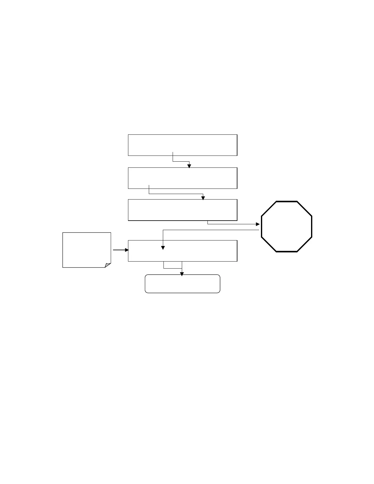
SAMPLE RANGE = 500.000 PPB SO2 =X.XXX
< TST TST > CAL
CALZ
CALS SETUP
ZERO CAL M
RANGE = 500.000 PPB SO2 =X.XXX
< TST TST >
ZERO
CONC
EXIT
WAIT 10
MINUTES
Or until the
reading
stabilizes and
the
ZERO
button
is displayed
Analyzer enters
ZERO CAL
Mode
See Table 5-1 for Z/S
Valve States during
this operating mode
SAMPLE
RANGE TO CAL: LOW
LOW
HIGH
ENTR SETUP
SAMPLE
RANGE TO CAL: HIGH
LOW HIGH
ENTR
SETUP