Optional Hardware and Software Model 100E Instruction Manual
50 045150102 Rev XB1
EXHAUST TO OUTER
LAYER OF KICKER
REACTION CELL PURGE
FLO
SENSO
FLOW / PRESSURE
SENSOR PCA
SAMPLE
FILTER
INSTRUMENT CHASSIS
EXHAUST GAS
OUTLET
VACUUM MANIFOLD
SAMPLE GAS
INLET
KICKER EXHAUST TO PUMP
PUMP
FLOW
CONTROL
ASSY
SAMPLE
PRESSURE
SENSOR
UV
LAMP
PMT
SAMPLE
CHAMBER
HYDROCARBON
SCRUBBER
(KICKER)
SPAN GAS INLET
ZERO AIR INLET
ZERO/SPAN
VALVE
2
3
1
SAMPLE/CAL
VALVE
3
2
1
IZS PERMEATION TUBE EXIT
IZS
Permeation Tube
NO
2
Source
ZERO AIR
SCRUBBER
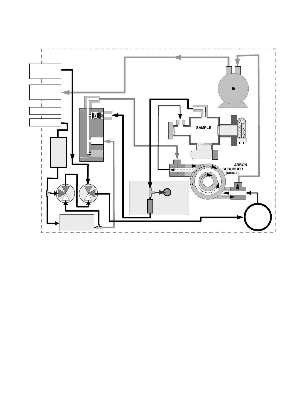
Figure 5-3: Pneumatic Diagram of the M100E with IZS Options Installed.
The state of the IZS valves can also be controlled:
• Manually from the analyzer’s front panel by using the SIGNAL I/O controls
located under the DIAG Menu (Section 6.7.2),
• By activating the instrument’s AutoCal feature (Section 7.8),
• Remotely by using the external digital control inputs (Section 6.8.2 and Section
7.7.1), or
• Remotely through the RS-232/485 serial I/O ports (see Appendix A-6 for the
appropriate commands).
External Zero Air Scrubber
The IZS option includes an external zero air scrubber assembly that removes all SO
2
the
zero air source. The scrubber is filled with activated charcoal.
The Permeation Source