Theory Of Operation Model 100E Instruction Manual
166 045150102 Rev XB1
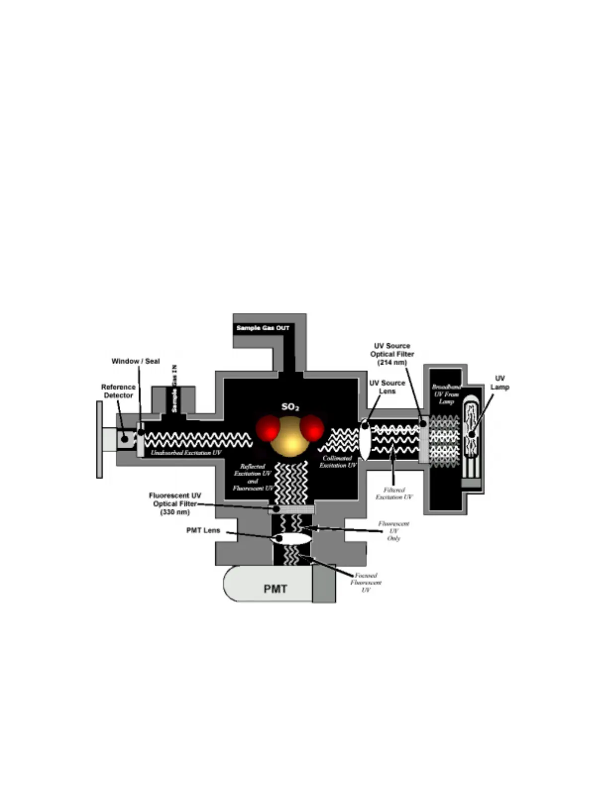
10.2. The UV Light Path
The optical design of the Model 100E’s sample chamber optimizes the fluorescent
reaction between SO
2
and UV Light (Figure 10-2) and assure that only UV light resulting
from the decay of SO
2
* into SO
2
is sensed by the instruments fluorescence detector.
UV radiation is generated by a lamp specifically designed to produce a maximum amount
of light of the wavelength needed to excite SO
2
into SO
2
* (330 nm) and a special
reference detector circuit constantly measures lamp intensity (see Equation 10-2). A
Photo Multiplier Tube (PMT) detects the UV given off by the SO
2
* decay (214 nm) and
outputs an analog signal. Several focusing lenses and optical filters make sure that both
detectors are exposed to an optimum amount of only the right wavelengths of UV. To
further assure that the PMT only detects light given off by decaying SO
2
* the pathway of
the excitation UV and field of view of the PMT are perpendicular to each other and the
inside surfaces of the sample chamber are coated with a layer of black Teflon
®
that
absorbs stray light.
Figure 10-2: UV Light Path
10.2.1. UV Source Lamp
The source of excitation UV light for the Model 100E is a low pressure zinc-vapor lamp.
An AC voltage heats up and vaporizes zinc contained in the lamp element creating a
light-producing plasma arc. Zinc-vapor lamps are preferred over the more common