Getting Started Model 100E Instruction Manual
40 045150102 Rev XB1
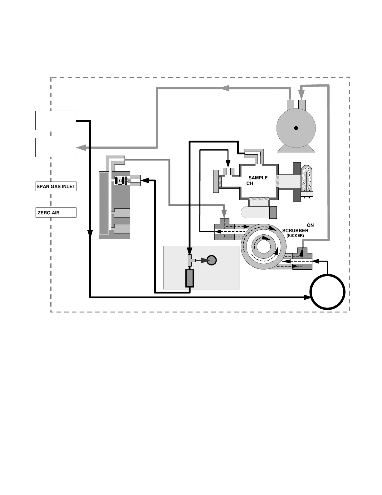
Figure 3-10 shows the internal gas flow diagram for the M100E in its basic configuration.
See Figures 5-2 and 5-3 for gas flow diagrams of units with valve options installed.
Refer to these diagrams whenever trouble-shooting or a thorough understanding of the
analyzer performance are required.
EXHAUST TO OUTER
LAYER OF KICKER
REACTION CELL PURGE
FLO
SENSOR
FLOW / PRESSURE
SENSOR PCA
SAMPLE
FILTER
INSTRUMENT CHASSIS
EXHAUST GAS
OUTLET
VACUUM MANIFOLD
SAMPLE GAS
INLET
KICKER EXHAUST TO PUMP
PUMP
FLOW
CONTROL
ASSY
SAMPLE
PRESSURE
SENSO
UV
LAMP
PMT
SAMPLE
CHAMBER
HYDROCARBON
SCRUBBER
(KICKER)
SPAN GAS INLET
ZERO AIR INLET
Figure 3-10: Pneumatic Diagram of the M100E Standard Configuration.