Model 100E Instruction Manual Getting Started
045150102 Rev XB1 29
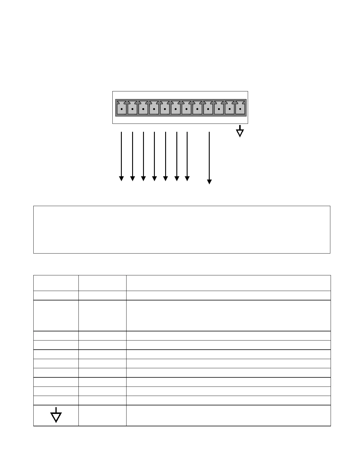
3.1.1.2. Connecting the Status Outputs
To utilize the analyzer’s status outputs are accessed through a 12 pin connector on the
analyzer’s rear panel labeled STATUS. They are used to interface with a device that
accepts logic-level digital inputs, such as programmable logic controllers (PLC’s).
Connect to Internal
Ground of Monitoring
STATUS
1 2 3 4 5 6 7 8 D
+
SYSTEM O
HIGH RANGE
CONC VALID
ZERO CAL
SPAN CAL
DIAGNOSTIC MODE
LOW SPAN
Figure 3-4: Status Output Connector
NOTE
Most PLC’s have internal provisions for limiting the current the input will draw. When
connecting to a unit that does not have this feature, external resistors must be used to
limit the current through the individual transistor outputs to ≤50mA (120 Ω for 5V
supply).
Table 3-2: Status Output Signals
Rear Panel
Label
Status
Definition
Condition
1 SYSTEM OK ON if no faults are present.
2 CONC VALID
OFF any time the HOLD OFF feature is active, such as during calibration
or when other faults exist possibly invalidating the current concentration
measurement (example: sample flow rate is outside of acceptable limits).
ON if concentration measurement is valid.
3 HIGH RANGE ON if unit is in high range of the AUTO Range Mode
4 ZERO CAL ON whenever the instrument’s ZERO point is being calibrated.
5 SPAN CAL ON whenever the instrument’s SPAN point is being calibrated.
6 DIAG MODE ON whenever the instrument is in DIAGNOSTIC mode
7 - 8 SPARE
D EMITTER BUS The emitters of the transistors on pins 1-8 are bussed together.
SPARE
+ DC POWER + 5 VDC, 300 mA source (combined rating with Control Output, if used).
Digital Ground The ground level from the analyzer’s internal DC power supplies