Operating Instructions Model 100E Instruction Manual
82 045150102 Rev XB1
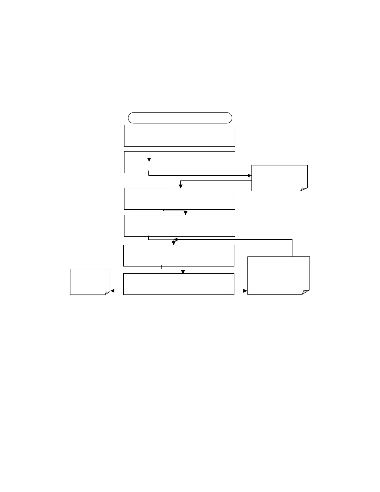
6.7.4.4. Analog Output Offset Adjustment
Some analog signal recorders require that the zero signal is significantly different from
the baseline of the recorder in order to record slightly negative readings from noise
around the zero point. This can be achieved in the M100E by defining a zero offset, a
small voltage (e.g., 10% of span), which can be added to the signal of individual output
channels by activating the ANALOG I/O CONFIGURATION MENU (see Section 6.7.1),
then pressing:
DIAG AIO
RECORD OFFSET: 0 MV
+ 0 0 0 0 ENTR EXIT
DIAG
ANALOG I / O CONFIGURATION
PREV
NEXT
ENTR
EXIT
DIAG AIO AOUTS CALIBRATED: NO
< SET
SET>
CAL
EXIT
FROM ANALOG I/O CONFIGURATION MENU
DIAG AIO
CONC_OUT_2 RANGE: 5V
SET> EDIT EXIT
Set the recorder
offset (in mV) of
the selected
channel
DIAG AIO
CONC_OUT_2:5V, CAL
< SET SET>
EDIT
EXIT
DIAG AIO
CONC_OUT_2 REC OFS: 0 mV
< SET SET>
EDIT
EXIT
Pressing
ENTR
accepts the
new setting and returns to the
previous menu.
Pressing
EXIT
ignores the new
setting and returns to the
previous menu.
Press
SET>
to select the
analog output channel to
be configured. Then press
EDIT
to continue
6.7.4.5. Current Loop Output Adjustment
A current loop option is available and can be installed as a retrofit for each of the analog
outputs of the analyzer (Sections 5-2). This option converts the DC voltage analog output
to a current signal with 0-20 mA output current. The outputs can be scaled to any set of
limits within that 0-20 mA range. However, most current loop applications call for either
2-20 mA or 4-20 mA range. All current loop outputs have a +5% over-range. Ranges
with the lower limit set to more than 1 mA (e.g., 2-20 or 4-20 mA) also have a -5%
under-range.
To switch an analog output from voltage to current loop after installing the current
output printed circuit assembly, follow the instructions in Section 6.7.4.1 and select
CURR from the list of options on the “Output Range” menu.
Adjusting the signal zero and span values of the current loop output is done by raising or
lowering the voltage of the respective analog output. This proportionally raises or lowers
the current produced by the current loop option.