Model 100E Instruction Manual Optional Hardware and Software
045150102 Rev XB1 47
5. OPTIONAL HARDWARE AND SOFTWARE
This section includes a descriptions of the hardware and software options available for
the Model 100E UV Fluorescence SO
2
Analyzer. For assistance with ordering these options
please contact the sales department of Teledyne - Advanced Pollution Instruments at:
TOLL-FREE: 800-324-5190
TEL: +1 858-657-9800
FAX: +1 858-657-9816
E-MAIL: apisales@teledyne.com
WEB SITE: http://www.teledyne-api.com/
5.1. Rack Mount Kits (Options 20a, 20b & 21)
There are several options for mounting the analyzer in standard 19” racks.
Option Number Description
OPT 20A Rack mount brackets with 26 in. chassis slides.
OPT 20B Rack mount brackets with 24 in. chassis slides.
OPT 21 Rack mount brackets only
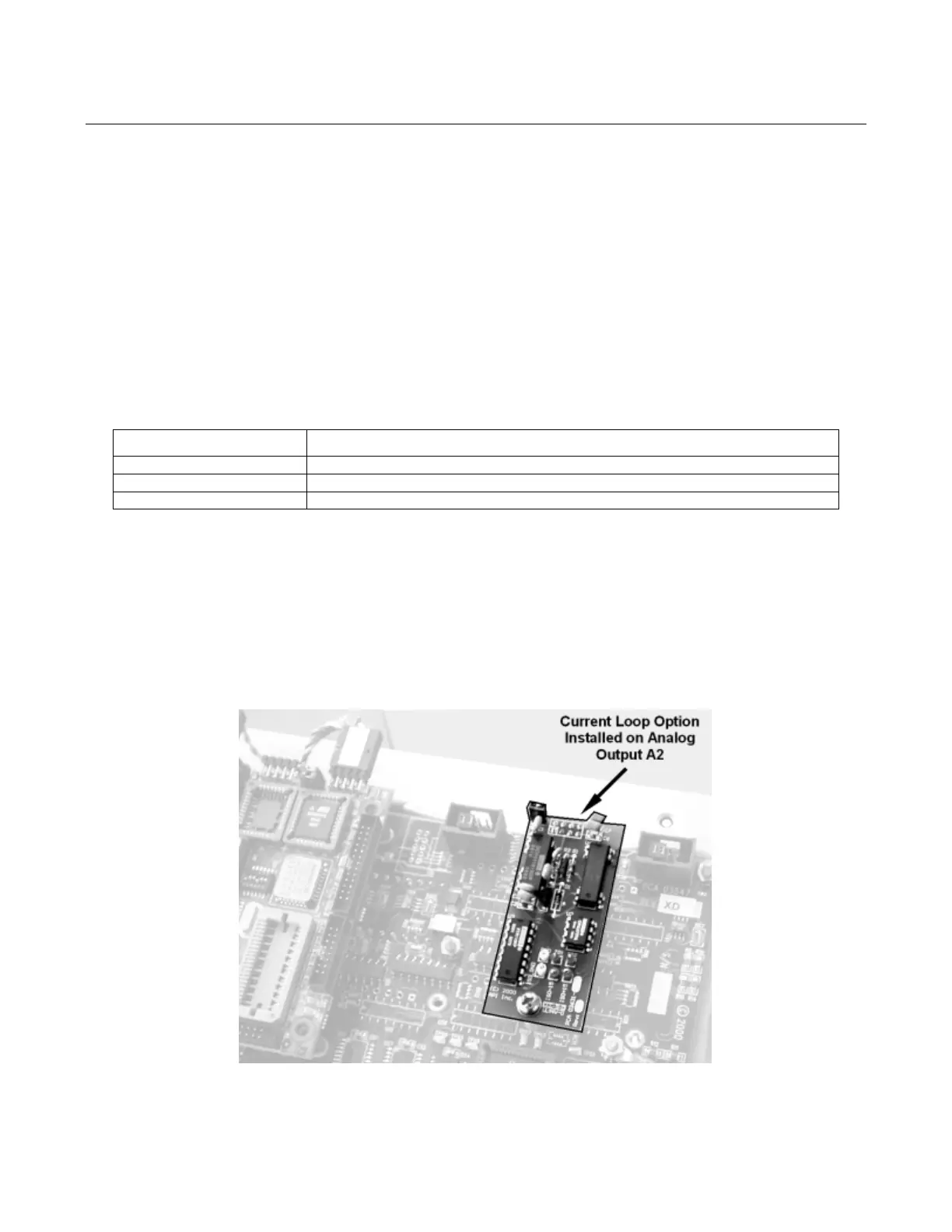
5.2. Current Loop Analog Outputs (Option 41)
This option adds isolated, voltage-to-current conversion circuitry to the analyzer’s analog
outputs. This option may be ordered separately for any of the analog outputs, it can be
installed at the factory or added later. Call T-API sales for pricing and availability.
The current loop option can be configured for any output range between 0 and 20 mA.
Information on calibrating or adjusting these outputs can be found in Section 6.7.4.5.
Figure 5-1: Current Loop Option Installed on the Motherboard