Getting Started Model 100E Instruction Manual
26 045150102 Rev XB1
Verify that all of the optional hardware ordered with the unit has been installed. These
are checked on the paperwork (Form 04551) accompanying the analyzer.
Once you have determined that no shipping damage exists and the unit includes all
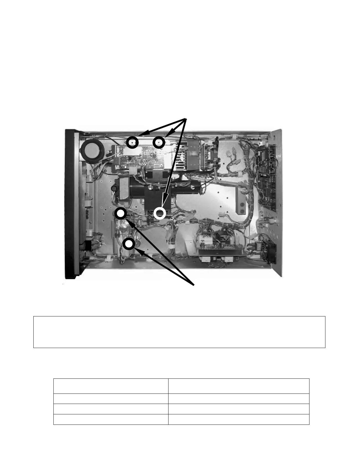
expected hardware options, remove three, RED colored shipping screws from the bottom
of the chassis, shown in Figure 3-1. There are:
• Three locking down the sample chamber sensor housing assembly.,
• Two locking down the internal pump visible from bottom of instrument).
Sensor Housing Shipping Screws
Remove from inside of instrument.
Pump Shipping Screws
Remove from outside, bottom of instrument.
Figure 3-1: Location of Shipping Screws
VENTILATION CLEARANCE: Whether the analyzer is set up on a bench or installed into
an instrument rack, be sure to leave sufficient ventilation clearance.
Area Minimum required clearance
Back of the instrument 10 cm / 4 inches
Sides of the instrument 2.5 cm / 1 inch
Above and below the instrument. 2.5 cm / 1 inch
NOTE
Save these shipping screws and re-install them whenever the unit is shipped.