Theory Of Operation Model 100E Instruction Manual
190 045150102 Rev XB1
10.6. Communications Interface
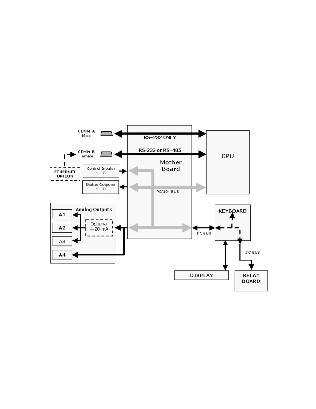
The analyzer has several ways to communicate the outside world, see Figure 10-19.
Users can input data and receive information directly through the front panel keypad and
display. Direct, two-way communication with the CPU is also available by way of the
analyzer’s RS232 & RS485 I/O ports (see Section 6.9 and 6.11). Alternatively, an
Ethernet communication option can be substituted for one of the Comm ports.
The analyzer can also send status information and data via the eight digital status output
lines (see Section 6.8.1) and the three analog outputs (see Section 6.5) located on the
rear panel as well as receive commands by way of the six digital control inputs also
located on the rear pane (see Section 6.8.2).
Figure 10-19: Interface Block Diagram