Model 100E Instruction Manual TROUBLESHOOTING & REPAIR
045150102 Rev XB1 211
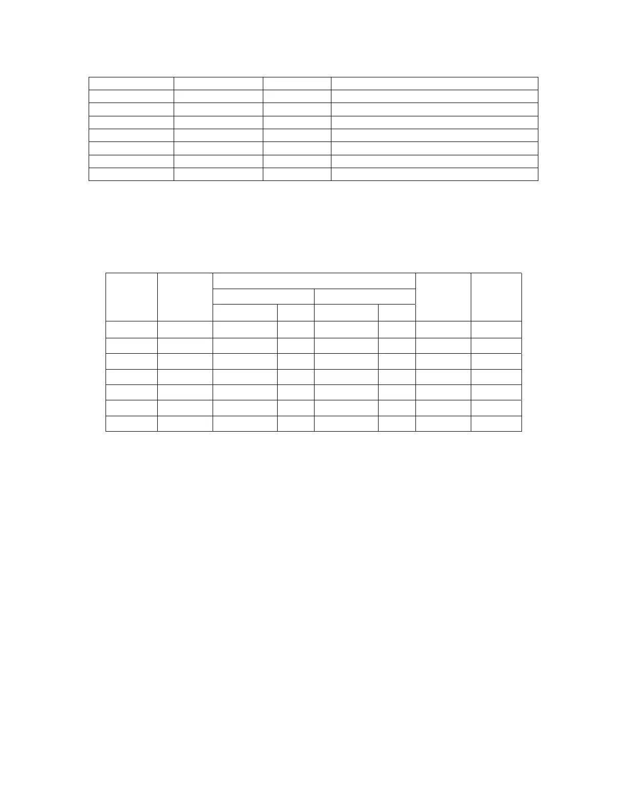
Table 11-3: DC Power Test Point and Wiring Color Code
NAME TEST POINT# COLOR DEFINITION
DGND 1 Black Digital ground
+5V 2 Red
AGND 3 Green Analog ground
+15V 4 Blue
-15V 5 Yellow
+12V 6 Purple
+12R 7 Orange 12 V return (ground) line
A voltmeter should be used to verify that the DC voltages are correct as listed in Table
11-4. An oscilloscope, in AC mode and with band limiting turned on, can be used to
evaluate if the supplies are excessively noisy (>100 mV peak-to-peak).
Table 11-4: DC Power Supply Acceptable Levels
CHECK relay board Test Points
From Test Point To Test Point
Power
Supply
Voltage
Name
#
Name
#
Min V Max V
PS1 +5 DGND
1 +5
2 +4.80 +5.25
PS1 +15 AGND 3 +15 4 +13.5 +16.0
PS1 -15 AGND 3 -15V 5 -14.0 -16.0
PS1 AGND AGND 3 DGND 1 -0.05 +0.05
PS1 Chassis DGND 1 Chassis N/A -0.05 +0.05
PS2 +12 +12V Ret 6 +12V 7 +11.8 +12.5
PS2 DGND +12V Ret 6 DGND 1 -0.05 +0.05
11.5.5. I
2
C Bus
Operation of the I
2
C bus can be verified by observing the behavior of the LED labeled D1
on the relay board in conjunction with the performance of the front panel display.
Assuming that the DC power supplies are operating properly and the wiring from the
motherboard to the keyboard as well as from the keyboard to the relay board is intact,
the I
2
C bus is operating properly if:
• D1 on the relay board is flashing or
• D1 is not flashing but pressing a key on the front panel results in a change to the
display.
If the display is locked up or if the analyzer is not booting up at all, the I
2
C bus may be
the cause. Contact customer service if you suspect a problem with the I
2
C bus.
11.5.6. Keyboard / Display Interface
The front panel keyboard, the display and the keyboard/display circuit board can be
verified by observing the operation of the display when power is applied to the