Operating Instructions Model 100E Instruction Manual
84 045150102 Rev XB1
If a current meter is not available, an alternative method for calibrating the current loop
outputs is to connect a 250 Ω ±1% resistor across the current loop output. Using a
voltmeter, connected across the resistor, follow the procedure above but adjust the
output to the following values:
Table 6-12: Current Loop Output Calibration with Resistor
Full scale
Voltage for 2-20 mA
(measured across resistor)
Voltage for 4-20 mA
(measured across resistor)
0% 0.5 V 1.0 V
100% 5.0 V 5.0 V
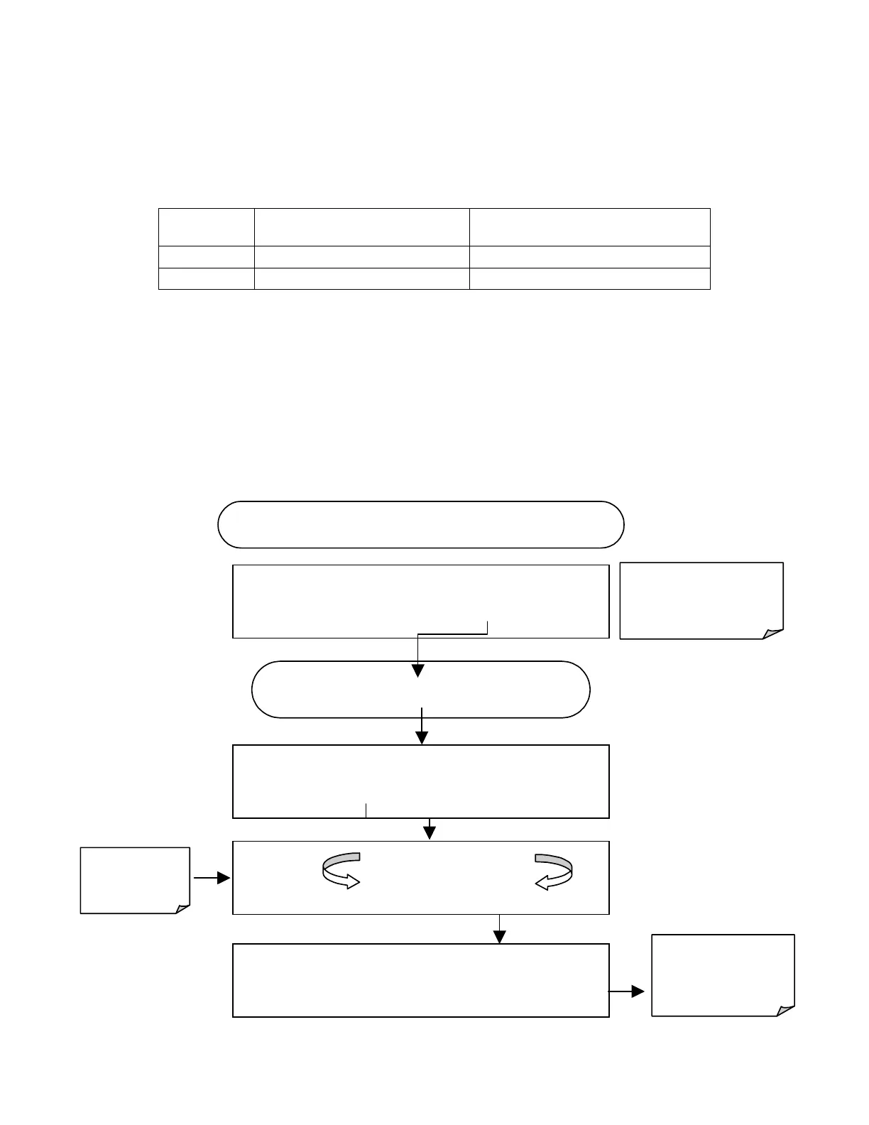
6.7.4.6. AIN Calibration
This is the sub-menu to conduct the analog input calibration. This calibration should only
be necessary after major repair such as a replacement of CPU, motherboard or power
supplies. Activate the ANALOG I/O CONFIGURATION MENU (see Section 6.7.1), then
press:
Exit at any time to
return to the main
DIAG
menu
DIAG
ANALOG I / O CONFIGURATION
PREV
NEXT
ENTR
EXIT
Continue pressing
SET?
until …
DIAG AIO
AIN CALIBRATED:
NO
< SET
SET>
CAL
EXIT
DIAG AIO AIN CALIBRATED:
YES
< SET
SET> CAL
EXIT
Instrument
calibrates
automatically
Exit to return to the
ANALOG I/O
CONFIGURATION
MENU
STARTING FROM ANALOG I / O CONFIGURATION MENU
DIAG AIO
CALIBRATING A/D ZERO
CALIBRATING A/D SPAN