Model 100E Instruction Manual Theory Of Operation
045150102 Rev XB1 185
10.4.9. Status LEDs & Watch Dog Circuitry
Zero/Span and IZS Options
Sample/CAL Valve
IZS Option
Permeation Tube Heater
Dark Shutter
Sample Chamber Heater
I2C Watchdog LED
Zero/Span and IZS Options
Zero/Span Valve
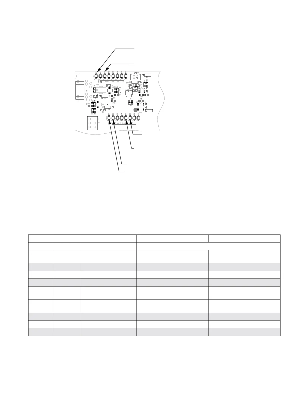
Figure 10-17: Relay Board Status LED Locations
Thirteen LEDs are located on the analyzer’s relay board to indicate the status of the
analyzer’s heating zones and valves as well as a general operating watchdog indicator.
Table 10-1 shows the states of these LEDs and their respective functionality.
Table 10-1: Relay Board Status LED’s
LED Color Function Status When Lit Status When Unlit
D1 RED Watchdog circuit Cycles On/Off every 3 seconds under control of the CPU.
D2 YELLOW
Sample chamber
heater
HEATING NOT HEATING
D3, D4 YELLOW Unused N/A N/A
D5 YELLOW IZS heater (option) HEATING NOT HEATING
D6 YELLOW Unused N/A N/A
D7 GREEN Autozero valve Valve open to vacuum
Valve open to sample
chamber
D8 GREEN SO
2
/SO
2
valve
Valve open to SO
2
converter
(SO
2
) gas
Valve open to SO
2
gas path
D9, D10 GREEN Unused N/A N/A
D11 GREEN UV Lamp Shutter Shutter open Shutter closed
D12-14 GREEN Unused N/A N/A
As a Safety measure, special circuitry on the Relay Board watches the status of LED D1.
Should this LED ever stay ON or OFF for 30 seconds, indicating that the CPU or I
2
C bus
 Loading...


