TROUBLESHOOTING & REPAIR Model 100E Instruction Manual
200 045150102 Rev XB1
• The technician can view the raw, unprocessed signal level of the analyzer’s critical
inputs and outputs.
• All of the components and functions that are normally under instrument control
can be manually changed.
• Analog and digital output signals can be manually controlled.
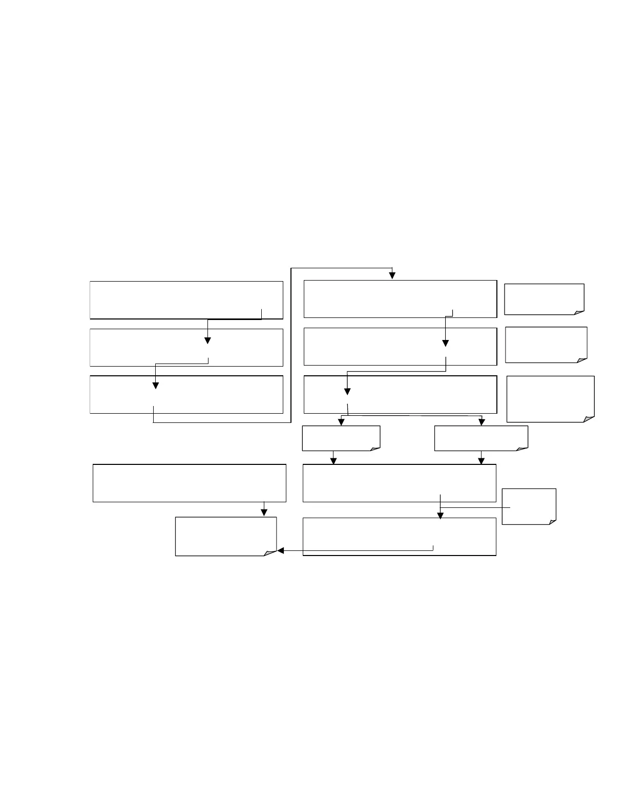
This allows to systematically observe the effect of these functions on the operation of the
analyzer. Figure 11-2 shows an example of how to use the signal I/O menu to view the
raw voltage of an input signal or to control the state of an output voltage or control
signal. The specific parameter will vary depending on the situation. Please note that the
analyzer will freeze it’s concentration output while in the diagnostic signal I/O menu.
This is because manually changing I/O outputs can invalidate the instrument reading.
Figure 11-2: Example of Signal I/O Function
SAMPLE RANGE = 500.0 PPB NOX=XXX.X
< TST TST > CAL
SETUP
SETUP
CFG DAS RNGE PASS CLK
MORE
EXIT
SETUP
COMM VARS
DIAG
HALT EXIT
Exit returns to
DIAG display & all values
return to software control
DIAG SIGNAL I/O
PREV NEXT
ENTR
EXIT
If parameter is an
input signal
DIAG I/O 0 ) EXT_ZERO_CAL=ON
PREV
NEXT
JUMP
PRNT EXIT
DIAG I/O 19
)
REACTION CELL_HEATER=
ON
PREV NEXT JUMP
ON
PRNT EXIT
SETUP ENTER DIAG PASS: 818
8 1 8
ENTR
EXIT
DIAG I/O 29) PMT_TEMP=378.3 MV
PREV NEXT
JUMP
PRNT EXIT
DIAG I/O 19
)
REACTION CELL_HEATER=
OFF
PREV NEXT JUMP
OFF
PRNT EXIT
If parameter is an output
signal or control
Toggles
parameter
ON/Off
Press ENTR to enter
the diagnostics menu
Press ENTR again to
enter the SIGNAL I/O
menu
Press PREV or NEXT
to scroll between
available I/O
parameters