Model 100E Instruction Manual TROUBLESHOOTING & REPAIR
045150102 Rev XB1 213
11.5.8. Motherboard
11.5.8.1. A/D functions
A basic check of the analog to digital (A/D) converter operation on the motherboard is to
use the Signal I/O function under the DIAG menu. Check the following two A/D
reference voltages and input signals that can be easily measured with a voltmeter.
• Using the Signal I/O function (Section 6.7.2 and Appendix D), view the value of
REF_4096_MV and REF_GND. If these signals are within 10 mV and 3 mV,
respectively, of their nominal values (4096 and 0) and are stable to within ±0.5
mV, the basic A/D converter is functioning properly. If these values fluctuate
largely or are off by more than specified above, one or more of the analog circuits
may be overloaded or the motherboard may be faulty.
• Choose one parameter in the Signal I/O function such as SAMPLE_PRESSURE
(see previous section on how to measure it). Compare its actual voltage with the
voltage displayed through the SIGNAL I/O function. If the wiring is intact but
there is a difference of more than ±10 mV between the measured and displayed
voltage, the motherboard may be faulty.
11.5.8.2. Analog Output Voltages
To verify that the analog outputs are working properly, connect a voltmeter to the output
in question and perform an analog output step test as described in Section 6.7.3.
For each of the steps, taking into account any offset that may have been programmed
into the channel (Section 6.7.4.4), the output should be within 1% of the nominal value
listed in the table below except for the 0% step, which should be within 2-3 mV. If one or
more of the steps is outside of this range, a failure of one or both D/A converters and
their associated circuitry on the motherboard is likely.
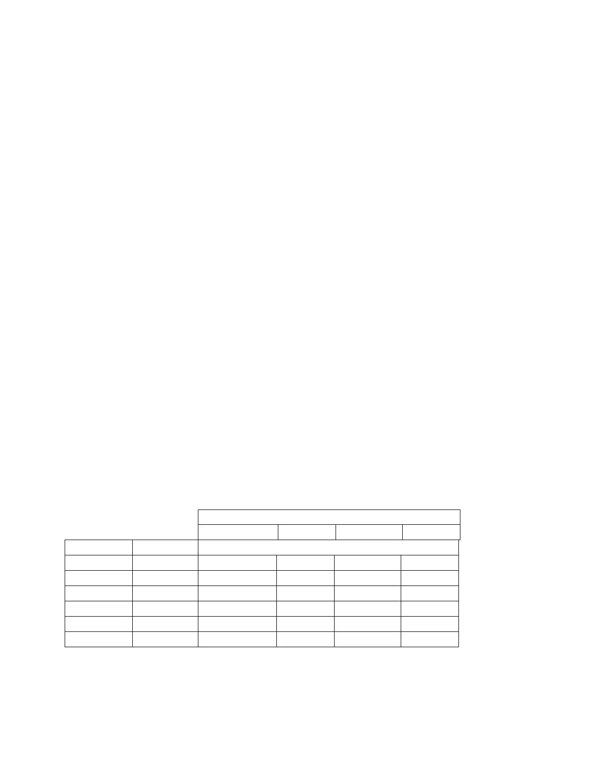
Table 11-6: Analog Output Test Function - Nominal Values
Full scale Output Voltage
100mV 1V 5V 10V
Step % Nominal Output Voltage
1 0 0 mV 0 0 0
2 20 20 mV 0.2 1 2
3 40 40 mV 0.4 2 4
4 60 60 mV 0.6 3 6
5 80 80 mV 0.8 4 8
6 100 100 mV 1.0 5 10