TROUBLESHOOTING & REPAIR Model 100E Instruction Manual
198 045150102 Rev XB1
are operating properly by checking the voltage test points on the relay board. Note
that the analyzer’s DC power wiring is color-coded and these colors match the
color of the corresponding test points on the relay board.
• Suspect a leak first! Customer service data indicate that half of all problems are
eventually traced to leaks in the pneumatic system of the analyzer (including the
external pump), the source of zero air or span gases or the sample gas delivery
system. Check for gas flow problems such as clogged or blocked internal/external
gas lines, damaged seals, punctured gas lines, a damaged pump diaphragm, etc.
• Follow the procedures defined in Section 11.5 for confirming that the analyzer’s
basic components are working (power supplies, CPU, relay board, keyboard, PMT
cooler, etc.). See Figure 3-8 for general layout of components and sub-assemblies
in the analyzer. See the wiring interconnect drawing and interconnect list, see
Appendix D.
11.1.1. Warning Messages
The most common and/or serious instrument failures will result in a warning message
displayed on the front panel. Table A-2 in Appendix A-3 contains a list of warning
messages, along with their meaning and recommended corrective action.
It should be noted that if more than two or three warning messages occur at the same
time, it is often an indication that some fundamental analyzer sub-system (power supply,
relay board, motherboard) has failed rather than an indication of the specific failures
referenced by the warnings. In this case, a combined-error analysis needs to be
performed.
The analyzer will alert the user that a warning is active by displaying the keypad labels
MSG and CLR on the front panel and a text message in the top center line of the display
as shown in this example:
SAMPLE AZERO WARNING NOX =123.4
< TST TST > CAL MSG CLR SETUP
The analyzer will also issue a message to the serial port and cause the red FAULT LED on
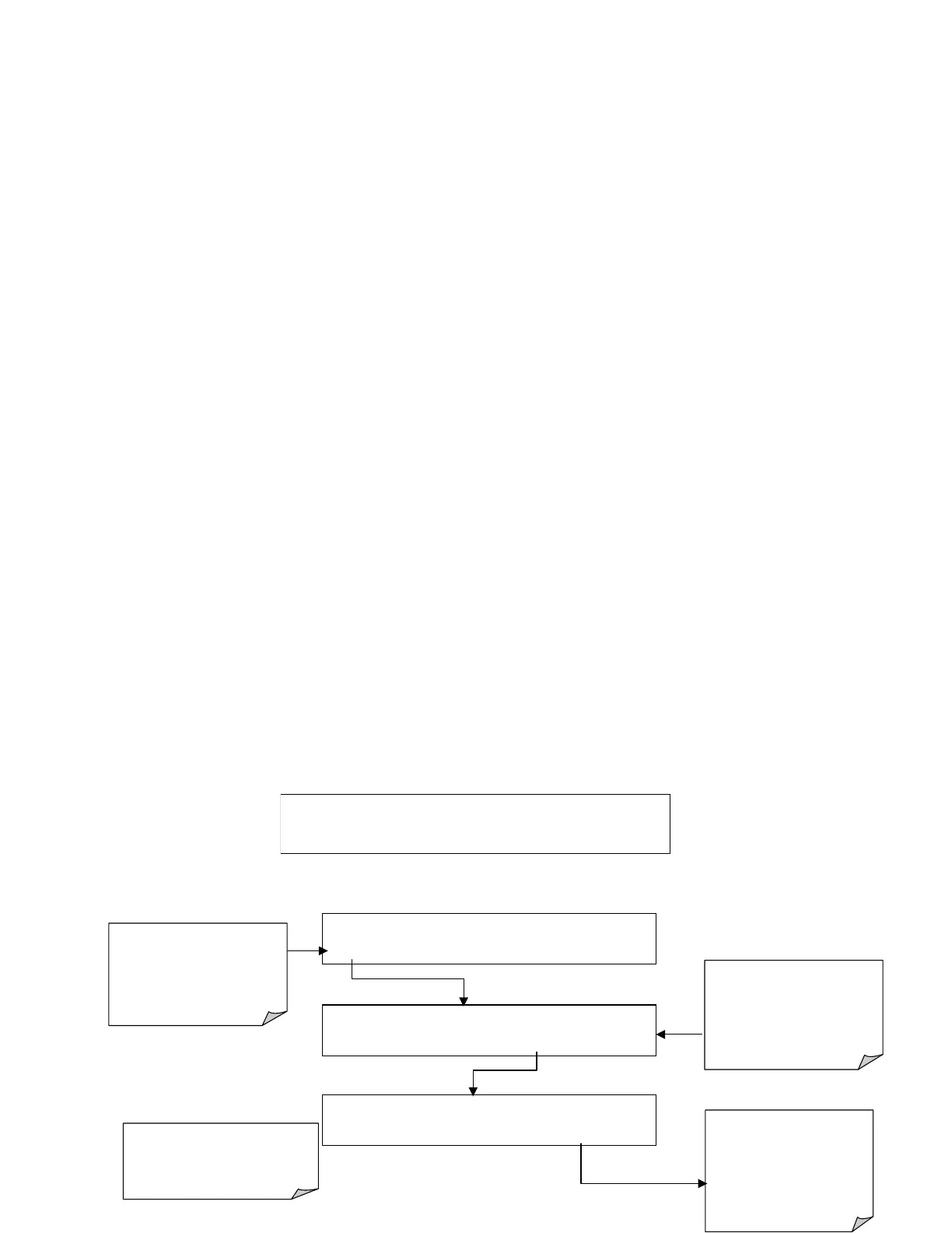
SAMPLE SYSTEM RESET NOX = XXX.X
TEST
CAL MSG CLR SETUP
If warning messages re-appear,
the cause needs to be found. Do
not repeatedly clear warnings
without corrective action.
Press
CLR
to clear the current
warning message.
If more than one warning is
active, the next message will
take its place.
Once the last warning has been
cleared, the analyzer returns to
SAMPLE Mode.
SAMPLE
RANGE=500 PPB
NOX = XXX.X
< TST TST > CAL
MSG
CLR SETUP
SAMPLE
SYSTEM RESET
NOX = XXX.X
< TST TST > CAL MSG
CLR
SETUP
In WARNING mode, <TST TST>
keys replaced with TEST key.
Pressing
TEST
switches to
SAMPLE mode and hides warning
messages until new warning(s)
are activated.
MSG
indicates that one or more
warning message are active but
hidden. Pressing MSG cycles
through warnings
In
SAMPLE
mode, all warning
messages are hidden, but MSG
button appears