Getting Started Model 100E Instruction Manual
28 045150102 Rev XB1
3.1.1.1. Connecting the Analog Outputs
Attach a strip chart recorder and/or data-logger to the appropriate contacts of the analog
output connecter on the rear panel of the analyzer.
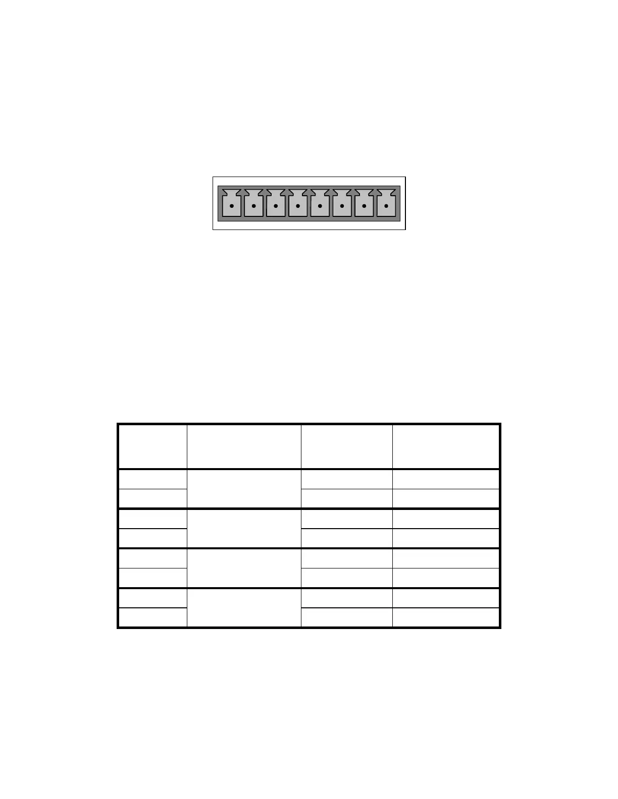
ANALOG OUT
A1 A2 A3 A4
+ - + - + - + -
Figure 3-3: Analog Output Connector
The A1 and A2 channels output a signal that is proportional to the SO
2
concentration of
the sample gas.
The output, labeled A4 is special. It can be set by the user (Section 6.7.10) to output
any one of the parameters accessible through the <TST TST> keys of the units sample
display.
Pin-outs for the Analog Output connector at the rear panel of the instrument are:
Table 3–1: Analog output Pin Outs
PIN ANALOG OUTPUT STANDARD
VOLTAGE
OUTPUT
CURRENT LOOP
OPTION
1 V Out I Out +
2
A1
Ground I Out -
3 V Out I Out +
4
A2
Ground I Out -
5 Not Available Not Available
6
A3
Not Available Not Available
7 V Out I Out +
8
A4
Ground I Out -
The default analog output voltage setting of the M100E UV Fluorescence SO2 Analyzer is
0 – 5 VDC with a range of 0 – 500 ppb.
TO change these settings, see Sections 6.5
An optional Current Loop output is available for each (See Section 5.2).