Theory Of Operation Model 100E Instruction Manual
180 045150102 Rev XB1
off of the instrument’s main AC power and are controlled by the CPU through a power
relay on the relay board. A thermistor, also embedded in the bottom of the sample
chamber, reports the cell’s temperature to the CPU through the thermistor interface
circuitry of the motherboard.
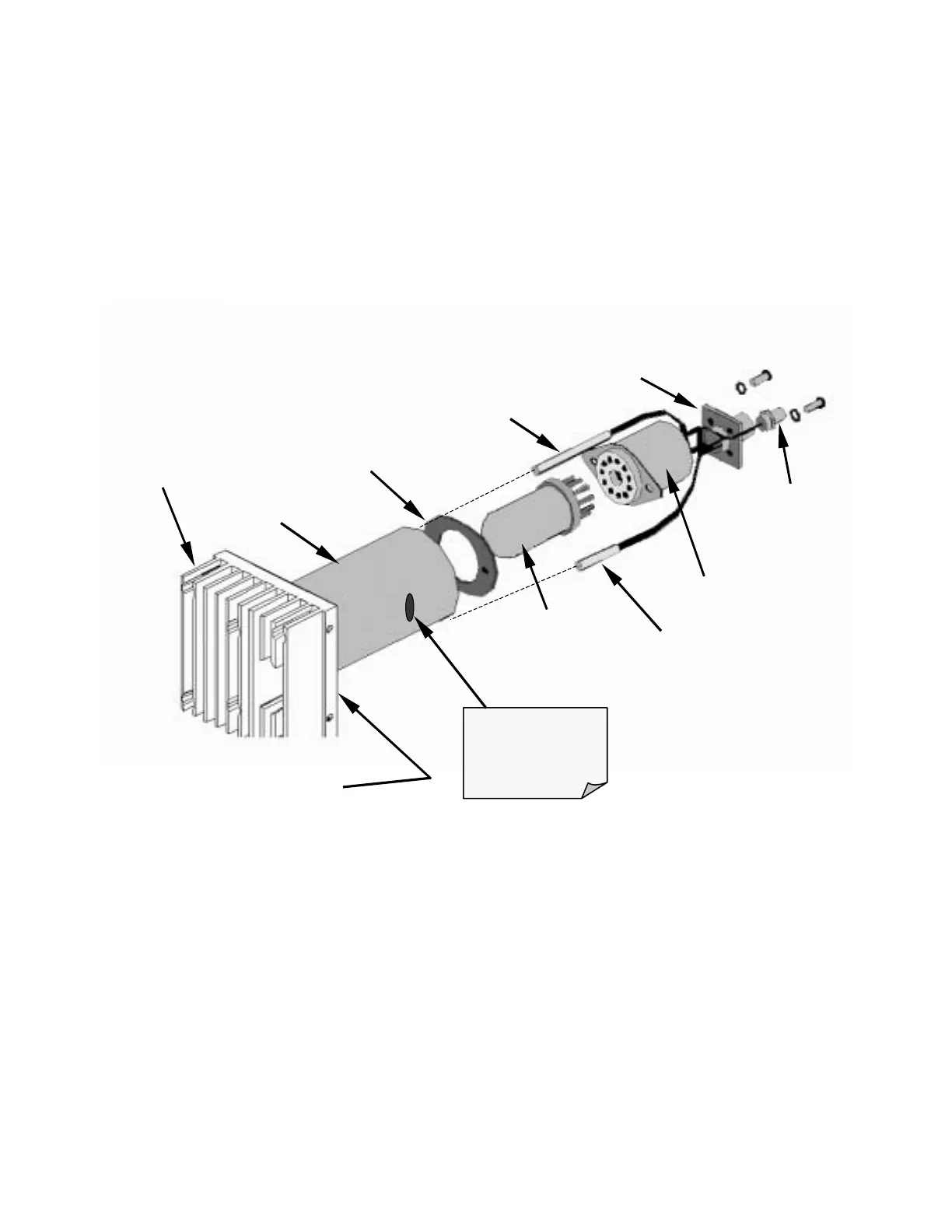
10.4.4. Photo Multiplier Tube (PMT)
The M100E uses a photo multiplier tube (PMT) to detect the amount of fluorescence
created by the SO
2
and O
3
reaction in the sample chamber.
PMT Input
Signal
Connector
Optical Test
LED
PMT
High Voltage
Power Supply
Insulator
Cold Block
PMT Temperature
Sensor
Heat Sink
PMT Output
Signal
Connector
TEC located
between Cold Block
and Heat
Sink
Light from Reaction
Chamber shines
through hole is side
of Cold Block
Figure 10-13: PMT Assembly
A typical PMT is a vacuum tube containing a variety of specially designed electrodes.
Photons from the reaction are filtered by an optical high-pass filter, enter the PMT and
strike a negatively charged photo cathode causing it to emit electrons. A high voltage
potential across these focusing electrodes directs the electrons toward an array of high
voltage dynodes. The dynodes in this electron multiplier array are designed so that each
stage multiplies the number of emitted electrons by emitting multiple, new electrons. The
greatly increased number of electrons emitted from one end of electron multiplier are
collected by a positively charged anode at the other end, which creates a useable current
signal. This current signal is amplified by the preamplifier board and then reported to the
motherboard.