Model 100E Instruction Manual Theory Of Operation
045150102 Rev XB1 189
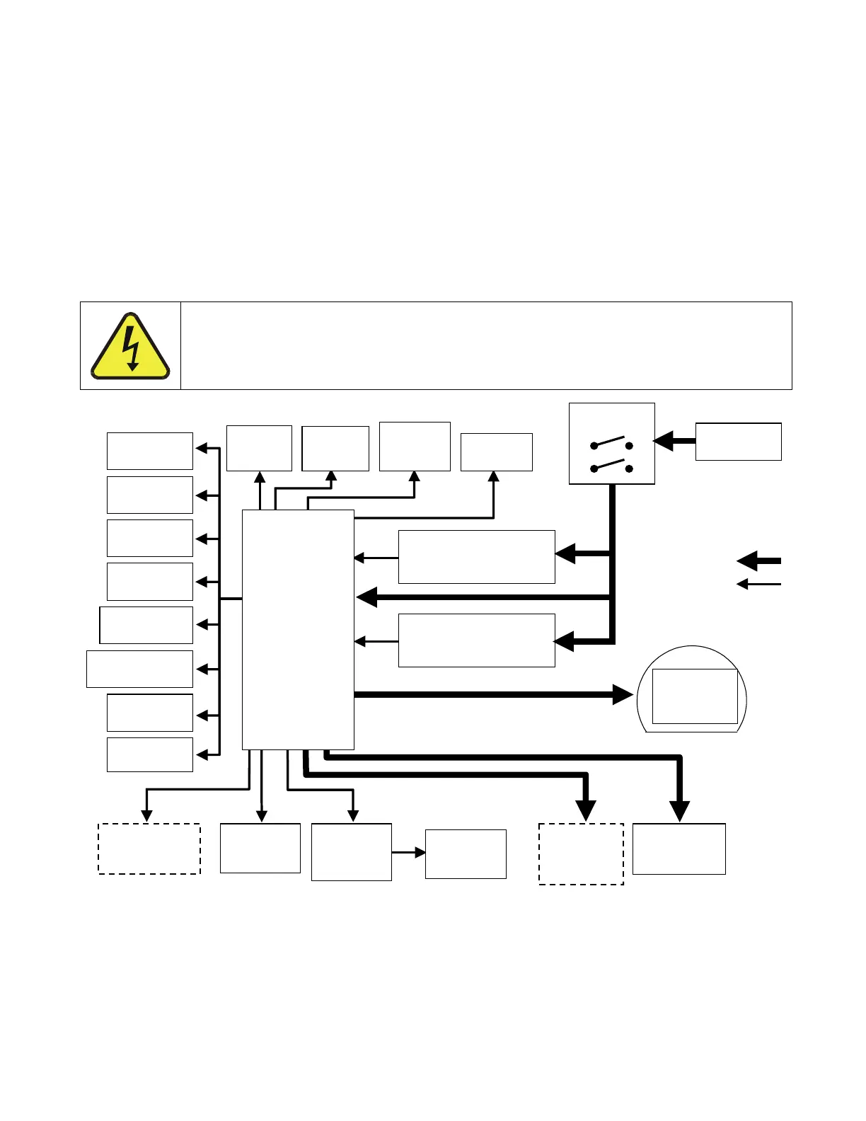
standard IEC 320 power receptacle located on the rear panel of the instrument. From
there it is routed through the ON/OFF switch located in the lower right corner of the front
panel.
AC line power is converted stepped down and converted to DC power by two DC power
supplies. One supplies +12 VDC, for various valves and valve options, while a second
supply provides +5 VDC and ±15 VDC for logic and analog circuitry as well as the TEC
cooler. All AC and DC Voltages are distributed through the Relay Board.
A 6.75 ampere circuit breaker is built into the ON/OFF switch. In case of a wiring fault or
incorrect supply power, the circuit breaker will automatically turn off the analyzer.
CAUTION
Should the power circuit breaker trip correct the condition causing this
situation before turning the analyzer back on.
AC POWER
ENTRANCE
ON/OFF
SWITCH
Pressure
Sensor
Mother
Board
CPU
PS 1 (+5 VDC; ±15 VDC)
PS 2 (+12 VDC)
Display
Keypad
Chassis
Cooling
Fan
PMT High
Voltage Supply
IZS Option
Permeation
Tube
Heater
PUMP
Temperature
Sensors
Gas Flow
Sensor
Sample
Chamber
Heaters
Sample/Cal
for Z/S and
IZS Valve
KEY
AC POWER
DC POWER
UV Source
Lamp
Power
Su
l
PMT
Cooling
Fan
PMT
Preamp
UV Source
Lamp
Shutter
RELAY
BOARD
TEC
Control
PCA
UV Source
Lamp
Shutter
Figure 10-18: Power Distribution Block Diagram